


Chapter 4
153
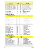
PostBDS POST Code Table
BDS_CONNECT_STD_ERR
BDS
18
Error report device initialization
BDS_CONNECT_USB_HC
BDS
19
USB host controller initialization
BDS_CONNECT_USB_BUS
BDS
1A
USB BUS driver initialization
BDS_CONNECT_USB_DEVICE
BDS
1B
USB device driver initialization
BDS_NO_CONSOLE_ACTION
BDS
1C
Console device initial fail
BDS_DISPLAY_LOGO_SYSTEM_INFO
BDS
1D
Display logo or system information
BDS_START_IDE_CONTROLLER
BDS
1E
IDE controller initialization
BDS_START_SATA_CONTROLLER
BDS
1F
SATA controller initialization
BDS_START_ISA_ACPI_CONTROLLER
BDS
20
SIO controller initialization
BDS_START_ISA_BUS
BDS
21
ISA BUS driver initialization
BDS_START_ISA_FDD
BDS
22
Floppy device initialization
BDS_START_ISA_SEIRAL
BDS
23
Serial device initialization
BDS_START_IDE_BUS
BDS
24
IDE device initialization
BDS_START_AHCI_BUS
BDS
25
AHCI device initialization
BDS_CONNECT_LEGACY_ROM
BDS
26
Dispatch option ROMs
BDS_ENUMERATE_ALL_BOOT_OPTION
BDS
27
Get boot device information
BDS_END_OF_BOOT_SELECTION
BDS
28
End of boot selection
BDS_ENTER_SETUP
BDS
29
Enter Setup Menu
BDS_ENTER_BOOT_MANAGER
BDS
2A
Enter Boot manager
BDS_BOOT_DEVICE_SELECT
BDS
2B
Try to boot system to OS
BDS_EFI64_SHADOW_ALL_LEGACY_RO
M
BDS
2C
Shadow Misc Option ROM
BDS_ACPI_S3SAVE
BDS
2D
Save S3 resume required data in
RAM
BDS_READY_TO_BOOT_EVENT
BDS
2E
Last Chipset initial before boot to
OS
BDS_GO_LEGACY_BOOT
BDS
2F
Start to boot Legacy OS
BDS_GO_UEFI_BOOT
BDS
30
Start to boot UEFI OS
BDS_LEGACY16_PREPARE_TO_BOOT
BDS
31
Prepare to Boot to Legacy OS
BDS_LEGACY_BOOT_EVENT
BDS
33
Last Chipset initial before boot to
Legacy OS.
BDS_ENTER_LEGACY_16_BOOT
BDS
34
Ready to Boot Legacy OS.
BDS_RECOVERY_START_FLASH
BDS
35
Fast Recovery Start Flash.
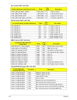
Functionality Name (Include\
PostCode.h)
Phase
Post
Cod
e
Description
POST_BDS_NO_BOOT_DEVICE
POST_BD
S
F9
No Boot Device
POST_BDS_START_IMAGE
POST_BD
S
FB
UEFI Boot Start Image
POST_BDS_ENTER_INT19
POST_BD
S
FD
Legacy 16 boot entry
POST_BDS_JUMP_BOOT_SECTOR
POST_BD
S
FE
Try to Boot with INT 19
Functionality Name (Include\
PostCode.h)
Phase
Post
Code
Description
Содержание ASPIRE 5251
Страница 6: ...VI...
Страница 10: ...X Table of Contents...
Страница 34: ...24 Chapter 1...
Страница 52: ...42 Chapter 2...
Страница 72: ...62 Chapter 3 3 Turn the computer over and disconnect the following four 4 cables from the Mainboard A B C D...
Страница 76: ...66 Chapter 3 5 Lift the Speaker clear of the Upper Cover...
Страница 78: ...68 Chapter 3 5 Lift the Right Speaker Module clear of the device...
Страница 84: ...74 Chapter 3 5 Lift the USB board clear of the device...
Страница 90: ...80 Chapter 3 11 Disconnect the Bluetooth to mainboard cable...
Страница 92: ...82 Chapter 3 4 Carefully lift the Thermal Module clear of the Mainboard...
Страница 103: ...Chapter 3 93 7 Disconnect the LVDS cable from the panel...
Страница 105: ...Chapter 3 95 5 Lift the microphone set and cable clear of the LCD cover...
Страница 114: ...104 Chapter 3 Replacing the Camera Module 1 Place the Camera in the module 2 Connect the camera cable...
Страница 121: ...Chapter 3 111 5 Connect the fan cable...
Страница 124: ...114 Chapter 3 6 Connect the LVDS cable to the mainboard 7 Connect the microphone cable...
Страница 127: ...Chapter 3 117 4 Connect the USB cable to the mainboard and lock the connector...
Страница 130: ...120 Chapter 3 4 Replace the FFC and press down as indicated to secure it to the Upper Cover...
Страница 135: ...Chapter 3 125 3 Connect the following cables to the Mainboard 4 Connect D as shown 5 Connect C as shown A B C D...
Страница 146: ...136 Chapter 3...
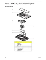
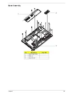
Страница 173: ...Chapter 6 163 Base Assembly No Description Acer P N 1 Logic Lower Door 2 3G Door 3 Lower Cover 1 2 3...
Страница 175: ...Chapter 6 165 Aspire 5251 5551G 5551 FRU List...
Страница 176: ...166 Chapter 6 Screw List...
Страница 177: ...Chapter 6 167...
Страница 206: ...196 Appendix C...
Страница 210: ...200...


