


28
Chapter 2
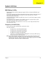
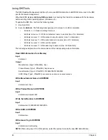
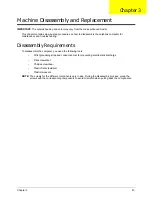
Security
The Security screen contains parameters that help safeguard and protect your computer from unauthorized
use.
NOTE:
System BIOS does not support Trusted Platform Module (TPM).
The table below describes the parameters in this screen. Settings in
boldface
are the default and suggested
parameter settings.
NOTE:
When prompted to enter a password, you have three tries before the system halts. If you forget your
password, you may have to return your notebook computer to your dealer to reset it.
Parameter
Description
Option
Supervisor Password Is
Shows the setting of the supervisor password
Clear
User Password Is
Shows the setting of the user password.
Clear
SATA Port 0 Disk Status
Shows the setting of the SATA Port Disk Status
Frozen
Set Supervisor Password
Press Enter to set the supervisor password. When
supervisor password is set, the BIOS Setup Utility is
protected from unauthorized access. The user can not
either enter the Setup menu nor change the value of
parameters.
N/A
Set User Password
Press Enter to set the user password. When user
password is set, this password protects the BIOS Setup
Utility from unauthorized access. The user can enter
Setup menu only and does not have right to change the
value of parameters except for the date and time.
N/A
Set SATA Port 0 HDD
Password
Enter SATA Port 0 HDD Password.
N/A
Power on Password
Defines whether a power on password is required.
When the system is first turned on it will prompt for a
password. Without a password the computer will not
continue to boot.
Disabled
or
Enabled
I t e m S p e c i f i c H e l p
I n s t a l l o r C h a n g e t h e
p a s s w o r d a n d t h e l e n g t h
o f p a s s w o r d m u s t b e
g r e a t e r t h a n o n e w o r d .
F 1
E S C
H e l p
E x i t
S e l e c t I t e m
S e l e c t M e n u
C h a n g e Va l u e s
S e l e c t
S u b M e n u
E n t e r
F 9
F 1 0
S e t u p D e f a u l t
S a v e a n d E x i t
C l e a r
C l e a r
F r o z e n
[ D i s a b l e d ]
C l e a r
C l e a r
F r o z e n
[ D i s a b l e d ]
S u p e r v i s o r P a s s w o r d I s
U s e r P a s s w o r d I s
S A T A P o r t 0 D i s k S t a t u s
S e t S u p e r v i s o r P a s s w o r d
S e t U s e r P a s s w o r d
S e t S A T A P o r t 0 H D D P a s s w o r d
P o w e r o n P a s s w o r d
S u p e r v i s o r P a s s w o r d I s
U s e r P a s s w o r d I s
S A T A P o r t 0 D i s k S t a t u s
S e t S u p e r v i s o r P a s s w o r d
S e t U s e r P a s s w o r d
S e t S A T A P o r t 0 H D D P a s s w o r d
P o w e r o n P a s s w o r d
F 5 / F 6
I n s y d e H 2 0 S e t u p U t i l i t y R e v . 3 . 5
Information
Main
Boot
Exit
Security
Содержание ASPIRE 5251
Страница 6: ...VI...
Страница 10: ...X Table of Contents...
Страница 34: ...24 Chapter 1...
Страница 52: ...42 Chapter 2...
Страница 72: ...62 Chapter 3 3 Turn the computer over and disconnect the following four 4 cables from the Mainboard A B C D...
Страница 76: ...66 Chapter 3 5 Lift the Speaker clear of the Upper Cover...
Страница 78: ...68 Chapter 3 5 Lift the Right Speaker Module clear of the device...
Страница 84: ...74 Chapter 3 5 Lift the USB board clear of the device...
Страница 90: ...80 Chapter 3 11 Disconnect the Bluetooth to mainboard cable...
Страница 92: ...82 Chapter 3 4 Carefully lift the Thermal Module clear of the Mainboard...
Страница 103: ...Chapter 3 93 7 Disconnect the LVDS cable from the panel...
Страница 105: ...Chapter 3 95 5 Lift the microphone set and cable clear of the LCD cover...
Страница 114: ...104 Chapter 3 Replacing the Camera Module 1 Place the Camera in the module 2 Connect the camera cable...
Страница 121: ...Chapter 3 111 5 Connect the fan cable...
Страница 124: ...114 Chapter 3 6 Connect the LVDS cable to the mainboard 7 Connect the microphone cable...
Страница 127: ...Chapter 3 117 4 Connect the USB cable to the mainboard and lock the connector...
Страница 130: ...120 Chapter 3 4 Replace the FFC and press down as indicated to secure it to the Upper Cover...
Страница 135: ...Chapter 3 125 3 Connect the following cables to the Mainboard 4 Connect D as shown 5 Connect C as shown A B C D...
Страница 146: ...136 Chapter 3...
Страница 173: ...Chapter 6 163 Base Assembly No Description Acer P N 1 Logic Lower Door 2 3G Door 3 Lower Cover 1 2 3...
Страница 175: ...Chapter 6 165 Aspire 5251 5551G 5551 FRU List...
Страница 176: ...166 Chapter 6 Screw List...
Страница 177: ...Chapter 6 167...
Страница 206: ...196 Appendix C...
Страница 210: ...200...


