


150
Chapter 4
Intermittent Problems
Intermittent system hang problems can be caused by a variety of reasons that have nothing to do with a
hardware defect, such as: cosmic radiation, electrostatic discharge, or software errors. FRU replacement
should be considered only when a recurring problem exists.
When analyzing an intermittent problem, do the following:
1.
Run the advanced diagnostic test for the system board in loop mode at least 10 times.
2.
If no error is detected, do not replace any FRU.
3.
If any error is detected, replace the FRU. Rerun the test to verify that there are no more errors.
Undetermined Problems
The diagnostic problems does not identify which adapter or device failed, which installed devices are incorrect,
whether a short circuit is suspected, or whether the system is inoperative.
Follow these procedures to isolate the failing FRU (do not isolate non-defective FRU).
NOTE:
Verify that all attached devices are supported by the computer.
NOTE:
Verify that the power supply being used at the time of the failure is operating correctly. (See “Power On
Issue” on page 138.):
1.
Power-off the computer.
2.
Visually check them for damage. If any problems are found, replace the FRU.
3.
Remove or disconnect all of the following devices:
•
Non-Acer devices
•
Printer, mouse, and other external devices
•
Battery pack
•
Hard disk drive
•
DIMM
•
CD-ROM/Diskette drive Module
•
PC Cards
4.
Power-on the computer.
5.
Determine if the problem has changed.
6.
If the problem does not recur, reconnect the removed devices one at a time until you find the failing FRU.
7.
If the problem remains, replace the following FRU one at a time. Do not replace a non-defective FRU:
•
System board
•
LCD assembly
Содержание ASPIRE 5251
Страница 6: ...VI...
Страница 10: ...X Table of Contents...
Страница 34: ...24 Chapter 1...
Страница 52: ...42 Chapter 2...
Страница 72: ...62 Chapter 3 3 Turn the computer over and disconnect the following four 4 cables from the Mainboard A B C D...
Страница 76: ...66 Chapter 3 5 Lift the Speaker clear of the Upper Cover...
Страница 78: ...68 Chapter 3 5 Lift the Right Speaker Module clear of the device...
Страница 84: ...74 Chapter 3 5 Lift the USB board clear of the device...
Страница 90: ...80 Chapter 3 11 Disconnect the Bluetooth to mainboard cable...
Страница 92: ...82 Chapter 3 4 Carefully lift the Thermal Module clear of the Mainboard...
Страница 103: ...Chapter 3 93 7 Disconnect the LVDS cable from the panel...
Страница 105: ...Chapter 3 95 5 Lift the microphone set and cable clear of the LCD cover...
Страница 114: ...104 Chapter 3 Replacing the Camera Module 1 Place the Camera in the module 2 Connect the camera cable...
Страница 121: ...Chapter 3 111 5 Connect the fan cable...
Страница 124: ...114 Chapter 3 6 Connect the LVDS cable to the mainboard 7 Connect the microphone cable...
Страница 127: ...Chapter 3 117 4 Connect the USB cable to the mainboard and lock the connector...
Страница 130: ...120 Chapter 3 4 Replace the FFC and press down as indicated to secure it to the Upper Cover...
Страница 135: ...Chapter 3 125 3 Connect the following cables to the Mainboard 4 Connect D as shown 5 Connect C as shown A B C D...
Страница 146: ...136 Chapter 3...
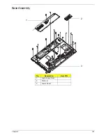
Страница 173: ...Chapter 6 163 Base Assembly No Description Acer P N 1 Logic Lower Door 2 3G Door 3 Lower Cover 1 2 3...
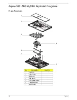
Страница 175: ...Chapter 6 165 Aspire 5251 5551G 5551 FRU List...
Страница 176: ...166 Chapter 6 Screw List...
Страница 177: ...Chapter 6 167...
Страница 206: ...196 Appendix C...
Страница 210: ...200...


