


198
LCD Brackets
Removing
91
Replacing
100
LCD Cable
Replacing
100
LCD Failure
141
LCD Module Disassembly
Flowchart
84
LCD Module Reassembly Procedure
98
LCD Panel
Removing
90
Replacing
100
Left Speaker Module
Removing
65
Replacing
123
M
Main Unit Disassembly
Flowchart
58
Mainboard
Removing
72, 73, 75, 76
Replacing
112
media access
on indicator
9
Memory
Replacing
130
Memory Check
138
Model Definition
168
N
No Display Issue
139
O
ODD Failure
145
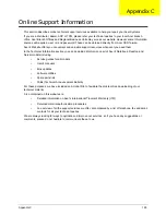
Online Support Information
195
Optical Disk Drive
Replacing
132, 133
Optical Drive Module
Removing
49
P
Panel
6
Bottom
9
PC Card
9
Power On Failure
138
R
Replacing
121, 123
Right Speaker Module
Removing
67
Replacing
121
S
SD Dummy Card
Removing
48
Replacing
134
Speakers
121, 123
Removing
65, 67
System
Block Diagram
5
T
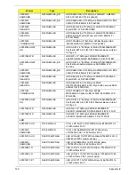
Test Compatible Components
187
Thermal Module
Removing
81
Replacing
110
Thermal Unit Failure
148
TouchPad
Removing
70
TouchPad Bracket
Removing
70
Replacing
119, 122
TouchPad Failure
142
Troubleshooting
Built-in KB Failure
141
EasyTouch Buttons
148
HDTV Switch
149
Internal Microphone
143
Internal Speakers
142
LCD Failure
141
No Display
139
ODD
145
Other Failures
149
Power On
138
Thermal Unit
148
TouchPad
142
WLAN
148
U
Undetermined Problems
150
Upper Cover
Содержание ASPIRE 5251
Страница 6: ...VI...
Страница 10: ...X Table of Contents...
Страница 34: ...24 Chapter 1...
Страница 52: ...42 Chapter 2...
Страница 72: ...62 Chapter 3 3 Turn the computer over and disconnect the following four 4 cables from the Mainboard A B C D...
Страница 76: ...66 Chapter 3 5 Lift the Speaker clear of the Upper Cover...
Страница 78: ...68 Chapter 3 5 Lift the Right Speaker Module clear of the device...
Страница 84: ...74 Chapter 3 5 Lift the USB board clear of the device...
Страница 90: ...80 Chapter 3 11 Disconnect the Bluetooth to mainboard cable...
Страница 92: ...82 Chapter 3 4 Carefully lift the Thermal Module clear of the Mainboard...
Страница 103: ...Chapter 3 93 7 Disconnect the LVDS cable from the panel...
Страница 105: ...Chapter 3 95 5 Lift the microphone set and cable clear of the LCD cover...
Страница 114: ...104 Chapter 3 Replacing the Camera Module 1 Place the Camera in the module 2 Connect the camera cable...
Страница 121: ...Chapter 3 111 5 Connect the fan cable...
Страница 124: ...114 Chapter 3 6 Connect the LVDS cable to the mainboard 7 Connect the microphone cable...
Страница 127: ...Chapter 3 117 4 Connect the USB cable to the mainboard and lock the connector...
Страница 130: ...120 Chapter 3 4 Replace the FFC and press down as indicated to secure it to the Upper Cover...
Страница 135: ...Chapter 3 125 3 Connect the following cables to the Mainboard 4 Connect D as shown 5 Connect C as shown A B C D...
Страница 146: ...136 Chapter 3...
Страница 173: ...Chapter 6 163 Base Assembly No Description Acer P N 1 Logic Lower Door 2 3G Door 3 Lower Cover 1 2 3...
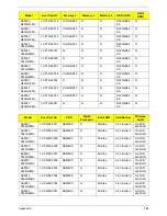
Страница 175: ...Chapter 6 165 Aspire 5251 5551G 5551 FRU List...
Страница 176: ...166 Chapter 6 Screw List...
Страница 177: ...Chapter 6 167...
Страница 206: ...196 Appendix C...
Страница 210: ...200...


