


Chapter 4
151
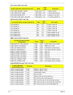
Post Codes
These tables describe the POST codes and descriptions during the POST.
Post Code Range
SEC Phase POST Code Table
PEI Phase POST Code Table:
Phase
POST Code Range
SEC
0x01 - 0x0F
PEI
0x70 - 0x9F
DXE
0x40 - 0x6F
BDS
0x10 - 0x3F
SMM
0xA0 - 0xBF
S3
0xC0 - 0xCF
ASL
0x51 – 0x55
0xE1 – 0xE4
PostBDS
0xF9 – 0xFE
Reserved
0xD8 – 0xE0
0xE5 – 0xE8
Functionality Name (Include\
PostCode.h)
Phase
Post
Code
Description
SEC_SYSTEM_POWER_ON
SEC
1
CPU power on and switch to
Protected mode
SEC_BEFORE_MICROCODE_PATCH
SEC
2
Patching CPU microcode
SEC_AFTER_MICROCODE_PATCH
SEC
3
Setup Cache as RAM
SEC_SETUP_CAR_OK
SEC
7
Cache as RAM test
SEC_GO_TO_SECSTARTUP
SEC
9
Setup BIOS ROM cache
SEC_GO_TO_PEICORE
SEC
0A
Enter Boot Firmware Volume
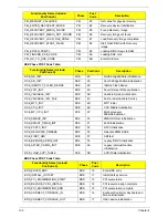
Functionality Name (Include\
PostCode.h)
Phase
Post
Code
Description
PEI_SIO_INIT
PEI
70
Super I/O Initialization
PEI_CPU_REG_INIT
PEI
71
CPU Early Initialization
PEI_CPU_AP_INIT
PEI
72
Multi-processor Early Initial
PEI_CPU_HT_RESET
PEI
73
HyperTransport Initialization
PEI_PCIE_MMIO_INIT
PEI
74
PCIE MMIO BAR Initialization
PEI_NB_REG_INIT
PEI
75
North Bridge Early Initialization
PEI_SB_REG_INIT
PEI
76
South Bridge Early Initialization
PEI_PCIE_TRAINING
PEI
77
PCIE Training
PEI_TPM_INIT
PEI
78
TPM Initialization
PEI_SMBUS_INIT
PEI
79
SMBUS Early Initialization
PEI_PROGRAM_CLOCK_GEN
PEI
7A
Clock Generator Initialization
PEI_MEMORY_INIT
PEI
7E
Memory Initial for Normal boot.
PEI_MEMORY_INIT_FOR_CRISIS
PEI
7F
Memory Initial for Crisis Recovery
PEI_MEMORY_INSTALL
PEI
80
Simple Memory test
PEI_SWITCH_STACK
PEI
82
Start to use Memory
Содержание ASPIRE 5251
Страница 6: ...VI...
Страница 10: ...X Table of Contents...
Страница 34: ...24 Chapter 1...
Страница 52: ...42 Chapter 2...
Страница 72: ...62 Chapter 3 3 Turn the computer over and disconnect the following four 4 cables from the Mainboard A B C D...
Страница 76: ...66 Chapter 3 5 Lift the Speaker clear of the Upper Cover...
Страница 78: ...68 Chapter 3 5 Lift the Right Speaker Module clear of the device...
Страница 84: ...74 Chapter 3 5 Lift the USB board clear of the device...
Страница 90: ...80 Chapter 3 11 Disconnect the Bluetooth to mainboard cable...
Страница 92: ...82 Chapter 3 4 Carefully lift the Thermal Module clear of the Mainboard...
Страница 103: ...Chapter 3 93 7 Disconnect the LVDS cable from the panel...
Страница 105: ...Chapter 3 95 5 Lift the microphone set and cable clear of the LCD cover...
Страница 114: ...104 Chapter 3 Replacing the Camera Module 1 Place the Camera in the module 2 Connect the camera cable...
Страница 121: ...Chapter 3 111 5 Connect the fan cable...
Страница 124: ...114 Chapter 3 6 Connect the LVDS cable to the mainboard 7 Connect the microphone cable...
Страница 127: ...Chapter 3 117 4 Connect the USB cable to the mainboard and lock the connector...
Страница 130: ...120 Chapter 3 4 Replace the FFC and press down as indicated to secure it to the Upper Cover...
Страница 135: ...Chapter 3 125 3 Connect the following cables to the Mainboard 4 Connect D as shown 5 Connect C as shown A B C D...
Страница 146: ...136 Chapter 3...
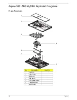
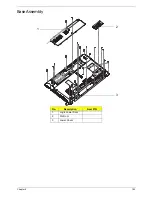
Страница 173: ...Chapter 6 163 Base Assembly No Description Acer P N 1 Logic Lower Door 2 3G Door 3 Lower Cover 1 2 3...
Страница 175: ...Chapter 6 165 Aspire 5251 5551G 5551 FRU List...
Страница 176: ...166 Chapter 6 Screw List...
Страница 177: ...Chapter 6 167...
Страница 206: ...196 Appendix C...
Страница 210: ...200...


