


138
Chapter 4
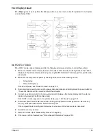
Power On Issue
If the system doesn’t power on, perform the following actions one at a time to correct the problem. Do not
replace a non-defective FRUs:
Computer Shutsdown Intermittently
If the system powers off at intervals, perform the following actions one at a time to correct the problem.
1.
Check the power cable is properly connected to the computer and the electrical outlet.
2.
Remove any extension cables between the computer and the outlet.
3.
Remove any surge protectors between the computer and the electrical outlet. Plug the computer directly
into a known good electrical outlet.
4.
Disconnect the power and open the casing to check the Thermal Unit (see “Thermal Unit Failure” on page
148) and fan airways are free of obstructions.
5.
Remove all external and non-essential hardware connected to the computer that are not necessary to
boot the computer to the failure point.
6.
Remove any recently installed software.
7.
If the Issue is still not resolved, see “Online Support Information” on page 195.
Содержание ASPIRE 5251
Страница 6: ...VI...
Страница 10: ...X Table of Contents...
Страница 34: ...24 Chapter 1...
Страница 52: ...42 Chapter 2...
Страница 72: ...62 Chapter 3 3 Turn the computer over and disconnect the following four 4 cables from the Mainboard A B C D...
Страница 76: ...66 Chapter 3 5 Lift the Speaker clear of the Upper Cover...
Страница 78: ...68 Chapter 3 5 Lift the Right Speaker Module clear of the device...
Страница 84: ...74 Chapter 3 5 Lift the USB board clear of the device...
Страница 90: ...80 Chapter 3 11 Disconnect the Bluetooth to mainboard cable...
Страница 92: ...82 Chapter 3 4 Carefully lift the Thermal Module clear of the Mainboard...
Страница 103: ...Chapter 3 93 7 Disconnect the LVDS cable from the panel...
Страница 105: ...Chapter 3 95 5 Lift the microphone set and cable clear of the LCD cover...
Страница 114: ...104 Chapter 3 Replacing the Camera Module 1 Place the Camera in the module 2 Connect the camera cable...
Страница 121: ...Chapter 3 111 5 Connect the fan cable...
Страница 124: ...114 Chapter 3 6 Connect the LVDS cable to the mainboard 7 Connect the microphone cable...
Страница 127: ...Chapter 3 117 4 Connect the USB cable to the mainboard and lock the connector...
Страница 130: ...120 Chapter 3 4 Replace the FFC and press down as indicated to secure it to the Upper Cover...
Страница 135: ...Chapter 3 125 3 Connect the following cables to the Mainboard 4 Connect D as shown 5 Connect C as shown A B C D...
Страница 146: ...136 Chapter 3...
Страница 173: ...Chapter 6 163 Base Assembly No Description Acer P N 1 Logic Lower Door 2 3G Door 3 Lower Cover 1 2 3...
Страница 175: ...Chapter 6 165 Aspire 5251 5551G 5551 FRU List...
Страница 176: ...166 Chapter 6 Screw List...
Страница 177: ...Chapter 6 167...
Страница 206: ...196 Appendix C...
Страница 210: ...200...


