


Chapter 4
139
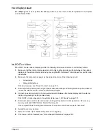
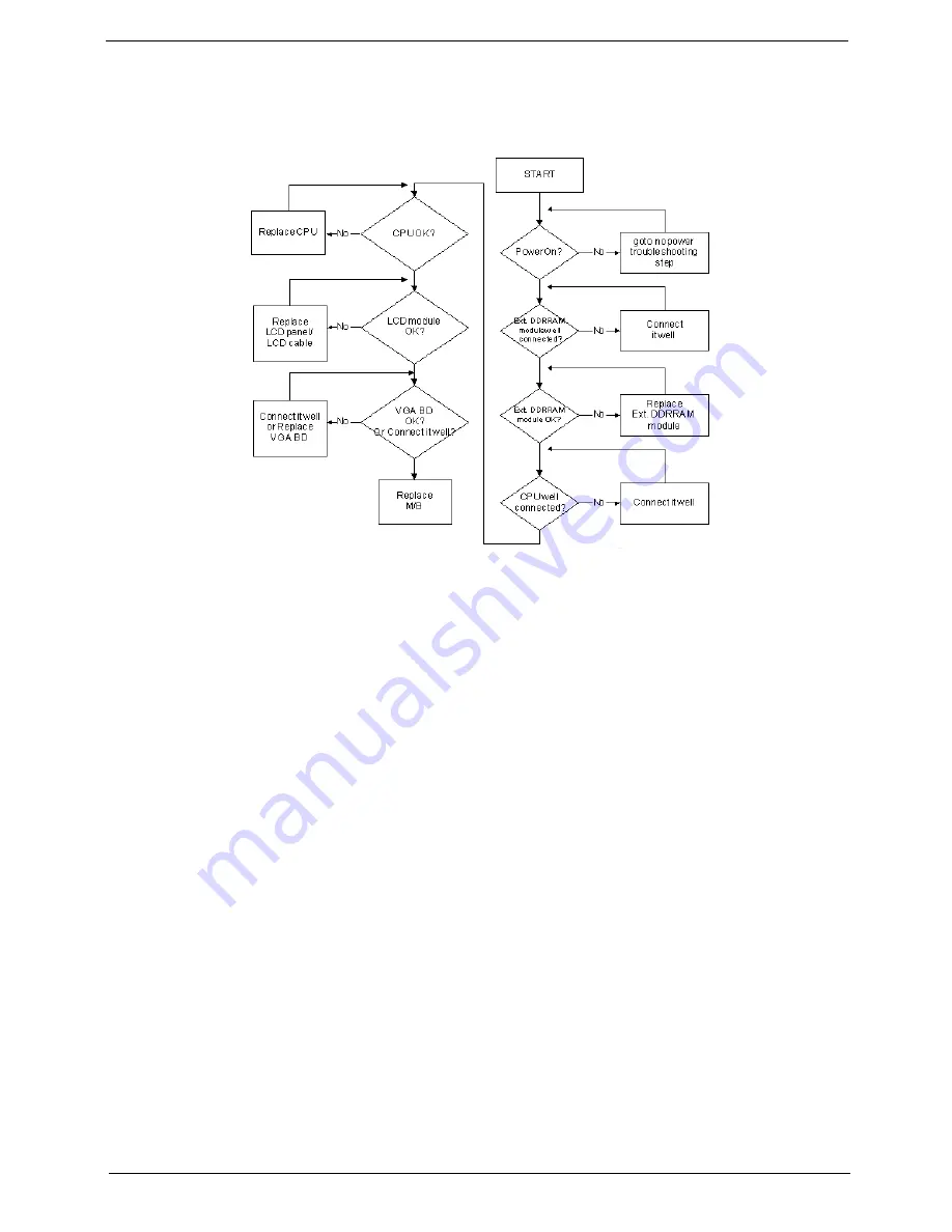
No Display Issue
If the
Display
doesn’t work, perform the following actions one at a time to correct the problem. Do not replace
a non-defective FRUs:
No POST or Video
If the POST or video doesn’t display, perform the following actions one at a time to correct the problem.
1.
Make sure that the internal display is selected. On this notebook model, switching between the internal
display and the external display is done by pressing
Fn+F5
. Reference Product pages for specific model
procedures.
2.
Make sure the computer has power by checking at least one of the following occurs:
•
Fans start up
•
Status LEDs light up
If there is no power, see “Power On Issue” on page 138.
3.
Drain any stored power by removing the power cable and battery and holding down the power button for
10 seconds. Reconnect the power and reboot the computer.
4.
Connect an external monitor to the computer and switch between the internal display and the external
display is by pressing
Fn+F5
(on this model).
If the POST or video appears on the external display, see “LCD Failure” on page 141.
5.
Disconnect power and all external devices including port replicators or docking stations. Remove any
memory cards and CD/DVD discs. Restart the computer.
If the computer boots correctly, add the devices one by one until the failure point is discovered.
6.
Reseat the memory modules.
7.
Remove the drives (see “Disassembly Process” on page 45).
8.
If the Issue is still not resolved, see “Online Support Information” on page 195.
Содержание ASPIRE 5251
Страница 6: ...VI...
Страница 10: ...X Table of Contents...
Страница 34: ...24 Chapter 1...
Страница 52: ...42 Chapter 2...
Страница 72: ...62 Chapter 3 3 Turn the computer over and disconnect the following four 4 cables from the Mainboard A B C D...
Страница 76: ...66 Chapter 3 5 Lift the Speaker clear of the Upper Cover...
Страница 78: ...68 Chapter 3 5 Lift the Right Speaker Module clear of the device...
Страница 84: ...74 Chapter 3 5 Lift the USB board clear of the device...
Страница 90: ...80 Chapter 3 11 Disconnect the Bluetooth to mainboard cable...
Страница 92: ...82 Chapter 3 4 Carefully lift the Thermal Module clear of the Mainboard...
Страница 103: ...Chapter 3 93 7 Disconnect the LVDS cable from the panel...
Страница 105: ...Chapter 3 95 5 Lift the microphone set and cable clear of the LCD cover...
Страница 114: ...104 Chapter 3 Replacing the Camera Module 1 Place the Camera in the module 2 Connect the camera cable...
Страница 121: ...Chapter 3 111 5 Connect the fan cable...
Страница 124: ...114 Chapter 3 6 Connect the LVDS cable to the mainboard 7 Connect the microphone cable...
Страница 127: ...Chapter 3 117 4 Connect the USB cable to the mainboard and lock the connector...
Страница 130: ...120 Chapter 3 4 Replace the FFC and press down as indicated to secure it to the Upper Cover...
Страница 135: ...Chapter 3 125 3 Connect the following cables to the Mainboard 4 Connect D as shown 5 Connect C as shown A B C D...
Страница 146: ...136 Chapter 3...
Страница 173: ...Chapter 6 163 Base Assembly No Description Acer P N 1 Logic Lower Door 2 3G Door 3 Lower Cover 1 2 3...
Страница 175: ...Chapter 6 165 Aspire 5251 5551G 5551 FRU List...
Страница 176: ...166 Chapter 6 Screw List...
Страница 177: ...Chapter 6 167...
Страница 206: ...196 Appendix C...
Страница 210: ...200...