Service and Maintenance
5-97
5.
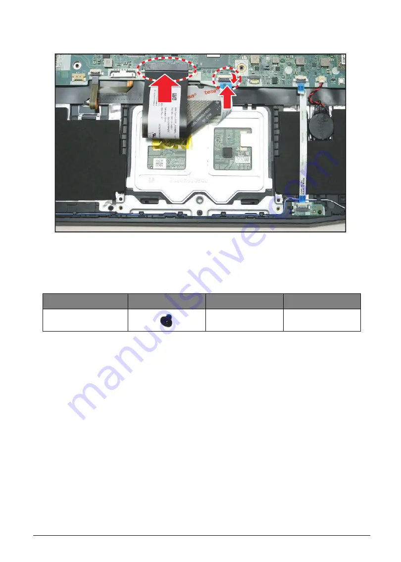
Connect the touchpad FFC from the mainboard connector and secure the latch. Then connect
the keyboard FPC to the mainboard connector.
Figure 5-146. Connecting the Cables
6.
Install the battery (see
).
Table 5-22. Touchpad Screws
Screw Name
Screw Type
Torque
Quantity
M 2.0 x 3.0
1.5~2.0kgf.cm
3
Содержание AN515-51
Страница 1: ...AN515 51 S E R V I C E G U I D E ...
Страница 13: ...Hardware Specifications and Configurations 1 6 Accessories 135W AC adapter Manual Kits Bag Power cord ...
Страница 22: ...1 15 Hardware Specifications and Configurations System Block Diagram Figure 1 7 System Block Diagram ...
Страница 141: ...CHAPTER 5 Service and Maintenance cont WLAN Antenna Aux Installation 5 128 ...
Страница 214: ...5 76 Service and Maintenance 5 Lift to remove the LCD module from the upper case Figure 5 109 Removing the LCD Module ...
Страница 292: ...CHAPTER 8 Online Support Information Online Support Information 8 2 Introduction 8 2 ...
Страница 294: ......


