Service and Maintenance
5-35
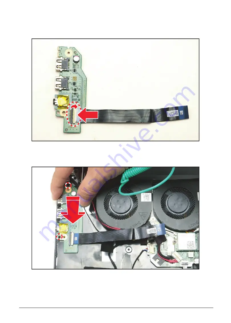
USB Board Installation
1.
Connect the USB board FFC to the USB board connector and secure the latch.
Figure 5-47. Connecting the USB Board FFC
2.
By aligning the USB board with the guide pins on the upper case, install the USB board onto its
slot on the upper case.
Figure 5-48. Installing the USB Board
Содержание AN515-51
Страница 1: ...AN515 51 S E R V I C E G U I D E ...
Страница 13: ...Hardware Specifications and Configurations 1 6 Accessories 135W AC adapter Manual Kits Bag Power cord ...
Страница 22: ...1 15 Hardware Specifications and Configurations System Block Diagram Figure 1 7 System Block Diagram ...
Страница 141: ...CHAPTER 5 Service and Maintenance cont WLAN Antenna Aux Installation 5 128 ...
Страница 214: ...5 76 Service and Maintenance 5 Lift to remove the LCD module from the upper case Figure 5 109 Removing the LCD Module ...
Страница 292: ...CHAPTER 8 Online Support Information Online Support Information 8 2 Introduction 8 2 ...
Страница 294: ......


