Service and Maintenance
5-5
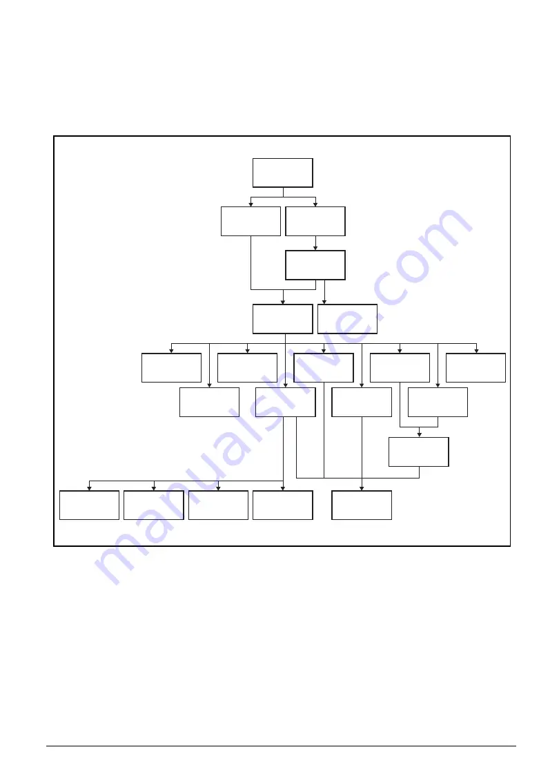
Maintenance Flowchart
The flowchart in
provides a graphic representation of the module
removal and installation sequences. It provides information on what components need to be
removed and installed during servicing.
Figure 5-1. Maintenance Flow
Mainboard
SSD Module
WLAN Module
USB Board
FAN1 Module
FAN2 Module
LCD Module
Thermal
Module
DC-IN Cable
HDD Cable
Battery
Hall Sensor
Board
RTC Battery
Speaker
Touchpad
DIMM Module
HDD Door
HDD Module
HDD Carrier
RAM Door
Lower Case
Содержание AN515-51
Страница 1: ...AN515 51 S E R V I C E G U I D E ...
Страница 13: ...Hardware Specifications and Configurations 1 6 Accessories 135W AC adapter Manual Kits Bag Power cord ...
Страница 22: ...1 15 Hardware Specifications and Configurations System Block Diagram Figure 1 7 System Block Diagram ...
Страница 141: ...CHAPTER 5 Service and Maintenance cont WLAN Antenna Aux Installation 5 128 ...
Страница 214: ...5 76 Service and Maintenance 5 Lift to remove the LCD module from the upper case Figure 5 109 Removing the LCD Module ...
Страница 292: ...CHAPTER 8 Online Support Information Online Support Information 8 2 Introduction 8 2 ...
Страница 294: ......


