37
3.2.9.
Hydraulic connections
Before installation, it is recommended to clean the system in order to eliminate any impurities that could come from the components and
which could damage the circulator and the exchanger.
HEATING
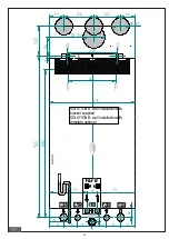
The central heating flow and return must be connected to the boiler to the respective 3/4”
M
and
R
fittings (fig. 7).
When sizing the heating circuit pipes, it is necessary to take into account the pressure drops induced by the radiators, by any thermostatic
valves, by the radiator stop valves and by the configuration of the system.
It is advisable to convey the discharge of the safety valve installed in the boiler to the sewer. In the
absence of this precaution, any intervention of the safety valve can cause flooding of the room in which
the boiler is installed.
The manufacturer is absolutely not responsible for damages caused by failure to observe this technical
precaution.
SANITARY
The cold water inlet and the domestic hot water outlet must be connected to the boiler to the respective 1/2”
C
and
F
fittings (fig. 7). The
hardness of the feed water conditions the frequency of cleaning and/or replacement of the secondary plate heat exchanger.
Depending on the hardness of the supply water, the advisability of installing suitable equipment for dosing
domestic use of food-grade products that can be used for the treatment of drinking water compliant with
current regulations must be evaluated.
With feed water with hardness higher than 20°F it is always advisable to treat the water. The water coming
from common softeners may, due to the pH values that characterize it, not be compatible with some
components of the heating system.
CONDENSATE DRAIN
For the evacuation of the condensate, comply with the laws and regulations in force which are understood to be fully transcribed here.
Unless particular prohibitions exist, the condensate produced during the combustion phase must be conveyed (by means of the
condensate drain) to a drain system which makes it flow to the domestic wastewater drain network which, due to its basic nature,
contrasts the acidity of the flue gas condensate. To avoid a return of bad odors from the domestic wastewater network, it is advisable to
add an odor trap between the condensate drainage system and the domestic wastewater network. The condensate drainage system and
the domestic wastewater drainage network must be constructed with suitable materials, resistant to attack by condensation water.
The condensate drain system must be connected to the special connection (A) set up in the boiler (see fig. 15).
It is absolutely forbidden to connect the condensate drain system to the siphon inspection point (B).
The manufacturer declines all responsibility for damage caused to people, animals or things deriving from
non-observance of the above.
3.2.10.
Connection to the electricity grid
The boiler must be connected to the 230V-50Hz power supply.
When connecting, respect the polarity by correctly connecting phase and neutral.
During the installation, comply with the regulations in force, which are understood to be fully transcribed here.
An easily accessible bipolar switch must be installed upstream of the boiler, which allows you to cut off the electricity supply and carry out
all maintenance operations in safety.
The boiler power supply line must be protected by a differential magneto-thermal switch with adequate breaking capacity. The power
supply network must have a secure earth connection. It is necessary to verify this fundamental safety requirement; if in doubt, request an
accurate check of the electrical system by professionally qualified personnel.
The manufacturer is absolutely not responsible for any damage caused by failure to earth the system: the
pipes of the gas, water and heating systems are not suitable as earth connections.
B
A
fig. 15
Содержание PLAY 24
Страница 45: ...45 3 6 3 Wiring diagram fig 21...
Страница 52: ......
Страница 53: ......
Страница 55: ...2...

