49
4.
Boiler testing
Each boiler is accompanied by a certificate of inspection.
Compiling the inspection certificate by an Authorized Assistance Center allows you to enjoy the advantages offered by the
insurance formula provided by the manufacturer as specified in the inspection certificate itself.
Filling out the inspection certificate is FREE.
4.1.
Preliminary checks
Before testing the boiler, it is advisable to check that:
- the smoke evacuation duct and the terminal part are installed in accordance with the instructions:
when the boiler is on, no leakage of
combustion products from any gasket is tolerated;
- the boiler power supply voltage is 230 V - 50 Hz;
- the system is correctly filled with water (pressure gauge 1÷1.3 bar);
- any shut-off cocks on the system pipes are open;
- the mains gas corresponds to the boiler calibration gas: otherwise, convert the boiler to use the available gas (see section 3.7):
this operation must be carried out by qualified technical personnel;
- the fuel supply cock is open;
- there are no fuel gas leaks;
- the main electric switch upstream of the boiler is on;
- the 3 bar safety valve is not blocked;
- there are no water leaks;
- the condensate drain siphon, fitted in the boiler, drains the condensate correctly and is not blocked.
If the boiler is not installed in compliance with the laws and regulations in force, notify the person in
charge of the system and do not test the boiler.
4.2.
Turning on and off
Follow the "
User Instructions
" to switch the boiler on and off.
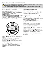
“ ” (D fig. 1) is used to switch between the Power / O2 menu (for cycle time).
“ ” or “ ” (
F
or
E
fig. 1) are used to increase / decrease the O2 value or change the system power (if the flame symbol flashes).
Premere, per il tempo ciclo, il tasto “
” (
D
fig. 1) per attivare il menu O
2
.
Premendo i tasti “
” o “
” (
F
o
E
fig. 1) sarà possibile modificare il valore corrente di RFlame set e variare la O
2
.
Premere il tasto “
”
for the cycle time) to confirm the regulation at “P0” and “
” (for the cycle time) to pass to the second level to be
regulated “P1”. Proceed with the CO2 calibration by following the steps taken to adjust the idle.
Press the " " key to confirm and the " " key to move on to setting the maximum "P2". Adjust the value as per the table Confirm with
the " " key.
Press the " " key (without waiting for the cycle time) to end the procedure and memorize the settings made.
ADJUSTMENT
MANU
The message “P0” appears on the display and the board is ready to adjust the CO2 value at minimum power.
With this condition:
“ ” (
D
fig. 1) is used to switch between the Power / CO
2
menu (for the cycle time).
“ ” or “ ” (F or E fig. 1) are used to increase / decrease the CO
2
value or change the system power (if the flame symbol flashes). For
the cycle time, press the " " key (D fig. 1) to activate the CO
2
menu.
By pressing the “ ” our “ ” keys (F or E fig. 1) it will be possible to modify the current value of RFlame set and correct the CO
2
.
Press the key " " (for the cycle time) to confirm the setting at "P0" and " " (for the cycle time) to pass to the second level to be
adjusted "P1". Proceed with the CO2 calibration by following the steps taken to adjust the idle.
Press the " " key to confirm and the " " key to move on to setting the maximum "P2". Adjust the value as per the table Confirm
with the " " key.
Press the " " key (without waiting for the cycle time) to end the procedure and memorize the settings made.
It is possible to exit the adjustment function at any time by pressing the " " key (A fig. 1) for the cycle time.
Содержание PLAY 24
Страница 45: ...45 3 6 3 Wiring diagram fig 21...
Страница 52: ......
Страница 53: ......
Страница 55: ...2...


