Publication No. HRMCP9 Rev. B
Specifications 73
8.11.3
Electrical Clearance
Starting with board version x.y certain rules on spacing between conductors on
individual layers of the printed circuit board (PCB) apply. The boards starting with
version V3.x are designed to meet the parameters as listed below.
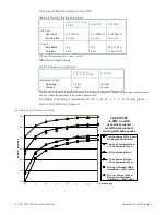
Voltage between conductors (DC or AC peaks) of 51 V – 100 V require a spacing of
- 0.6 mm for type B2 conditions
external conductors, uncoated, sea level to 3050 m.
These rules are in accordance with IPC-2221 requirements.
8.11.4
Isolation
The Isolation of the Ethernet outputs whether front or rear is limited to 500 V peak
against GND and any other supply voltage.
By itself the onboard digital ground GND and the front panel/chassis frame ground
FGND are isolated on the CR9 with a layout distance of more than 0.3 mm in all PCB
layers. However, most standard devices (keyboard, mouse, and monitor) except
Ethernet will connect FGND and GND directly in the device. Also standard racks
(our starter cage too) connect both grounds at the power supply for safety reasons.
Содержание CR9 Series
Страница 24: ...24 CP9 CR9 CT9 Celeron M Pentium M Publication No HRMCP9 Rev B Figure 2 2 Handling the CR9 Board ...
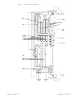
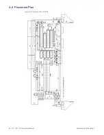
Страница 77: ...Publication No HRMCP9 Rev B Transition Module CTM12 77 Figure A 1 CTM12 Component Locations ...
Страница 90: ...90 CP9 CR9 CT9 Celeron M Pentium M Publication No HRMCP9 Rev B Figure B 1 Mount PMC Board to CR9 ...

