34 CP9*, CR9*, CT9* Celeron M/Pentium M
Publication No. HRMCP9 Rev. B
5 •
Interfaces
This chapter describes the interfaces of the CR9 CompactPCI Single Board Computer
located on the board and on the front panel. Each section on a particular interface
includes a graphics illustration of the connector and a pin assignment table as well as
notes on certain signal line characteristics, if necessary.
For interfaces of the transition module, please refer to the appropriate chapters
Figure 5-1 Location of Components on Board and Front Panel
5.1 Front Panel Interfaces
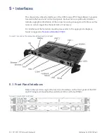
Refer to the next drawing for the location of interfaces on the front panel of the CR9
and CT9 single slot board (either with front I/O or with dual PMC):
Figure 5-2 Single Slot Front Panel
Содержание CR9 Series
Страница 24: ...24 CP9 CR9 CT9 Celeron M Pentium M Publication No HRMCP9 Rev B Figure 2 2 Handling the CR9 Board ...
Страница 77: ...Publication No HRMCP9 Rev B Transition Module CTM12 77 Figure A 1 CTM12 Component Locations ...
Страница 90: ...90 CP9 CR9 CT9 Celeron M Pentium M Publication No HRMCP9 Rev B Figure B 1 Mount PMC Board to CR9 ...


