Publication No. HRMCP9 Rev. B
Interfaces 41
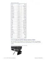
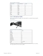
Figure 5-6 Keyboard and Mouse Connector Layout
Table 5-5 Keyboard and Mouse Pin Assignments
Name
P2001
Keyboard Data
1
Mouse Data
2
GND
3
Fused +5 V
a
4
Keyboard Clk
5
Mouse Clk
6
a
the Fused +5 V pin is fused with a 2 A fuse. For normal operation don’t exceed 100 mA current. The used fuse
does automatically recover if the over current is resolved.
5.2.6
Ethernet Interface U5600 and U5650
The Ethernet output front or rear can be selected via order. When ordered with front
option, the connectors are located in the front panel.
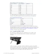
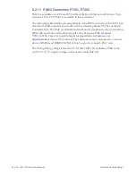
Figure 5-7 Ethernet Connector Location
Figure 5-8 Ethernet Connector Layout
Содержание CR9 Series
Страница 24: ...24 CP9 CR9 CT9 Celeron M Pentium M Publication No HRMCP9 Rev B Figure 2 2 Handling the CR9 Board ...
Страница 77: ...Publication No HRMCP9 Rev B Transition Module CTM12 77 Figure A 1 CTM12 Component Locations ...
Страница 90: ...90 CP9 CR9 CT9 Celeron M Pentium M Publication No HRMCP9 Rev B Figure B 1 Mount PMC Board to CR9 ...


