48 CP9*, CR9*, CT9* Celeron M/Pentium M
Publication No. HRMCP9 Rev. B
5.2.12
PMC I/O Connector P6204 and P7204
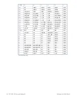
Pin 1 of the I/O connector is PMCxIO_01; Pin 2 is PMCxIO_02 and so on. The x
denotes PMC1 or PMC2 respectively. All traces are not connected to any signal
onboard and no pairs or length adjusted traces are used to route this signals to the
backplane connectors.
5.3 Transition Module
Please refer to the appendix chapters for interface location and connector pin
assignments for the optional extension boards and transition modules.
Содержание CR9 Series
Страница 24: ...24 CP9 CR9 CT9 Celeron M Pentium M Publication No HRMCP9 Rev B Figure 2 2 Handling the CR9 Board ...
Страница 77: ...Publication No HRMCP9 Rev B Transition Module CTM12 77 Figure A 1 CTM12 Component Locations ...
Страница 90: ...90 CP9 CR9 CT9 Celeron M Pentium M Publication No HRMCP9 Rev B Figure B 1 Mount PMC Board to CR9 ...

