Publication No. HRMCP9 Rev. B
Specifications 71
•
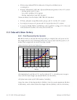
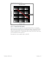
0.5 m/s airflow means convection cooled only with free airflow. This is the
minimum required airflow for the CR9.
•
The core temperature of the CPU can be read out via the onboard temperature
sensor. The value must be kept below 100 °C for all operating conditions. This
value is already included in the airspeed diagram above. If this temperature limit
is violated, the Pentium CPUs will start to reduce its internal frequency
temporarily. This can be heard by a short click of the speaker which occurs every
0.8 seconds. The Celeron processor will not automatically switch down to lower
frequencies but will stop its internal clock in preprogrammed intervals.
•
In the diagram above you can find two temperature limits. One shows the
maximum operating temperature when using graphics with 3D applications or
the TMDS interface. The other shows the limit with the graphics option mounted
or when using the Ethernet interface with both channel in Gigabit mode. For Fast
Ethernet (100 Mbit). This limit needs not to be taken into consideration. Both
limits are valid with the low power CPUs running at 600 MHz or 1100 MHz. For
higher CPU frequencies, the maximum operating temperature is limited by the
CPU already.
•
When using an onboard hard disk drive (not with flash disk) the operating
temperature is limited to 50 °C
•
When using one or two PMC modules, please consider their power consumption
and thermal limits in calculating the max. operating temperature
8.10.1
Card Edge Temperatures for CR9 Style 8
Table 8-6 Card Edge Temperatures
Processor
Operating
Temperature
Pentium M, 1.6 GHz (130 nm)
67°C
Pentium M (745), 1.8 GHz (90 nm)
72°C
Celeron M (320), 1.3 GHz (130 nm)
76°C
Low Voltage Pentium M, 1.1 GHz (130 nm)
83°C
Low Voltage Pentium M (738), 1.4 GHz (90 nm)
85°C
Ultra Low Voltage Celeron M 600 MHz (130 nm)
85°C
Ultra Low Voltage Celeron M (373) 1 GHz (90 nm)
85°C
These values do not include temperature variations due to PMC modules.
For more information on the N-, 8-style version, please check the thermal report
document of the CR9.
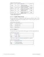
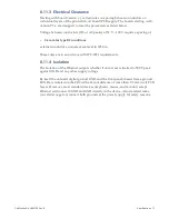
8.11 Electrical Characteristics
The supply voltages are +5 V, +3.3 V, +12 V. The -12 V are required only if needed on
the PMC slot. All Output voltages of the CR9 boards have an over current
protection. The maximum current for each voltage is shown below:
Содержание CR9 Series
Страница 24: ...24 CP9 CR9 CT9 Celeron M Pentium M Publication No HRMCP9 Rev B Figure 2 2 Handling the CR9 Board ...
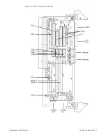
Страница 77: ...Publication No HRMCP9 Rev B Transition Module CTM12 77 Figure A 1 CTM12 Component Locations ...
Страница 90: ...90 CP9 CR9 CT9 Celeron M Pentium M Publication No HRMCP9 Rev B Figure B 1 Mount PMC Board to CR9 ...

