Publication No. HRMCP9 Rev. B
Transition Module CTM12 81
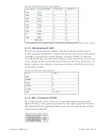
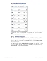
Table A-5 COM1/COM2 Connector Pin Assignments
Name RS232
Name RS422/485
COM2 P2203
P2200,2201
DCD
TXD-
1
1
DSR
TXD+
6
2
RXD
RTS-
2
3
RTS
RTS+
7
4
TXD
CTS+
3
5
CTS
CTS-
8
6
DTR
RXD+
4
7
RI
RXD-
9
8
GND
GND
5
9
FUSE_VCC
a
-
10
a
+5 V supplied by the CR9 and fused with max 2 A at CTM12 for normal operation don’t exceed 100 mA at this pin.
A.1.5 VGA Interface P4001
The VGA monitor signals are available on P4100 a 10-pin male header. They are
parallel connected with the DVI-I connector P4100. You either can use a DVI display
on P4100 or a standard VGA Monitor/Display connected to P4001 or a standard
VGA Monitor/Display via a DVI-to-VGA adaptor connected to P4100. You never can
use two display devices connected to the transition module. If you want to have two
display outputs, you will have to connect one to the front of the CR9 and one to the
rear/transition module.
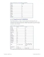
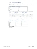
Table A-6 VGA Connector Pin Assignments
Name
P4001
RED
2
GREEN
4
BLUE
6
HSYNC
8
VSYNC
10
GND
1, 3, 5, 7, 9
A.1.6 DVI-I Connector P4100
The CTM12 provides a DVI-I connector to connect DVI capable monitors. Both
digital and analog video signals are provided. For the digital signals the Transition
Minimized Differential Signaling (TMDS) is used. The maximum resolution with a
CR9 is limited to 1024x768.
Figure A-3 DVI Connector Layout
Содержание CR9 Series
Страница 24: ...24 CP9 CR9 CT9 Celeron M Pentium M Publication No HRMCP9 Rev B Figure 2 2 Handling the CR9 Board ...
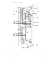
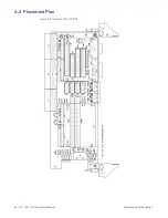
Страница 77: ...Publication No HRMCP9 Rev B Transition Module CTM12 77 Figure A 1 CTM12 Component Locations ...
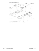
Страница 90: ...90 CP9 CR9 CT9 Celeron M Pentium M Publication No HRMCP9 Rev B Figure B 1 Mount PMC Board to CR9 ...

