30 CP9*, CR9*, CT9* Celeron M/Pentium M
Publication No. HRMCP9 Rev. B
4 •
Getting Started
This chapter gives some useful tips when using a board from CR9 family the first
time. It might be also useful to read this chapter carefully, when problems came up
in using the CR9.
4.1 Power Supply
All boards of the Cx family require up to 50 Watts from the power supply. For exact
values please check the actual datasheet, but for rough data a current of up to 7 A at
the 5 V rail and 12 A at the 3.3 V rail must be taken into consideration. The +12 V
must only supply a few mA and is not very critical. If there are hard disks or PMC
modules attached to the CR9, then their power consumption must also be calculated.
Keep in mind, that standard power supplies often require minimum loads on every
supply voltage for proper operation. It might be necessary to add a load to the +12 V
to ensure correct voltage levels on 3.3 V and 5 V.
If you ever see the board not starting well or doing resets at random states, please
check the voltage of the three supply voltages at the backplane. When measuring
there, you can use a standard digital multimeter and you have to attach it to the
backplane at positions where no high current is flowing. So better use rear contacts
of the bus connectors or unused power connectors to measure, because measuring
the voltages at the used power connectors can result in wrong values, which are
caused by the high current flowing.
The +12 V are less critical, but 5 V and 3.3 V should reach their nominal value when
measuring with a multimeter. If the voltages are less than 5.0 V or 3.3 V, then short
voltage drops while the CPU or memory gets into high activities may result in
resetting the CR9 board.
4.2 Status Indicator, Postcode and Beeps
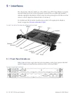
The CR9 family has a dual color LED at the front panel for a quick status indicator
usage. The possible colors are red, orange or green and the LED can blink in
different frequencies or be on continuously.
The CR9, CP9, CT9 additional have a blue Hot Swap LED as required according to
the PICMG specification. This blue LED is also an indication for a reset condition.
While running its BIOS initialization all boards of the CR9 family write postcodes
(POST = Power-On Self Test) to port 80h at the PCI bus 0 (at PMC2). These accesses
can be monitored with appropriate equipment or a PMC post card. For easier access
the postcodes are sent also to the parallel port LPT1 data lines. When measuring
their values or adding 8 LEDs with current limiting resistors to GND, you can follow
the POST sequence of the BIOS. When the boot process stops at a certain point also
the eight voltage levels can be measured with a multimeter.
Содержание CR9 Series
Страница 24: ...24 CP9 CR9 CT9 Celeron M Pentium M Publication No HRMCP9 Rev B Figure 2 2 Handling the CR9 Board ...
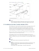
Страница 77: ...Publication No HRMCP9 Rev B Transition Module CTM12 77 Figure A 1 CTM12 Component Locations ...
Страница 90: ...90 CP9 CR9 CT9 Celeron M Pentium M Publication No HRMCP9 Rev B Figure B 1 Mount PMC Board to CR9 ...

