32 CP9*, CR9*, CT9* Celeron M/Pentium M
Publication No. HRMCP9 Rev. B
Table 4-1 Boot Timing
Time after
releasing
PCI reset
POSTCODE
Status LED
Comment
1 µs
D0
Red 1 Hz blinking
726 ms
AC
Orange 1 Hz blinking
All memory is initialized
3.9 s
1
D4
8.4 s
D6
12.2 s
D7
12.3 s
03
Green 1 Hz blinking
Keyboard enabled
2
12.7 s
4013
Green 2 Hz blinking
15.2 s
202A
Video Bios is started
3
16.9 s
3C
Green 3 Hz blinking
17.2 s
78
Starting external BIOS
4
17.2 s
8C
Green 4 Hz blinking
17.3 s
00
Green steady on
Try booting from mass storage
1
from here add 2.9 seconds for 2 GByte of memory
2
now is the right point to press DEL if you want to go to BIOS SETUP
3
CRT and/or panel are now initialized and show the startup screen
4
external BIOS from add on cards i.e. SCSI
Depending on the monitor/display type it may need some additional seconds until
you can see something on the screen.
4.4 Setup
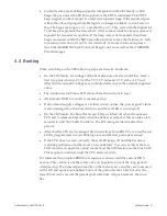
When you want to enter the BIOS Setup, you have to press the keyboard ‘DEL’ key
at the right moment. Especially when using a slow starting monitor it might be too
late to wait for the CRT to show the message ‘Press DEL to enter Setup’. Better look
for the LED and press ‘DEL’ as soon as the LED goes from orange to green blinking.
When you are using add on cards with external BIOS, you can hit the DEL key while
their BIOS runs (i.e. SCSI BIOS device scan).
When you miss the right moment to press the DEL key, please use the reset button
on the front panel to restart the power up sequence or switch off the power supply
for a few seconds and restart it. With the current BIOS pressing the Ctrl-Alt-Del key
combination at this boot-moment will result in switching to the next bootable device
and try to boot from this. This feature cannot be disabled within Setup.
4.5 Hot Swap on CR9
The CR9 family supports full Hot Swap according to CPCI specification 2.1. This
includes all hardware functionality to detect other bus cards or devices to be
plugged in or removed while the system is running under power. Also the CR9 can
be hot plugged to a running system or be removed from it.
Содержание CR9 Series
Страница 24: ...24 CP9 CR9 CT9 Celeron M Pentium M Publication No HRMCP9 Rev B Figure 2 2 Handling the CR9 Board ...
Страница 77: ...Publication No HRMCP9 Rev B Transition Module CTM12 77 Figure A 1 CTM12 Component Locations ...
Страница 90: ...90 CP9 CR9 CT9 Celeron M Pentium M Publication No HRMCP9 Rev B Figure B 1 Mount PMC Board to CR9 ...

