


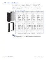

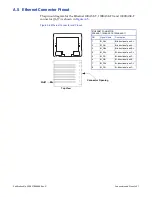
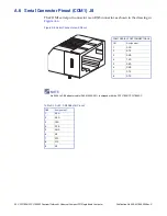
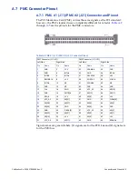


Publication No. 500-657806-000 Rev. G
Embedded PC/RTOS Features 49
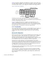
maps the configuration possibilities for a typical system consisting of
the CPCI-7806/CPCI-7806RC with a resident CompactFlash, a hard drive attached
to the Primary IDE interface, and a floppy drive attached to the floppy interface.
Figure 3-2 Typical System Configuration
The Primary and Secondary PCI IDE Interfaces are controlled (enabled or
disabled) in the ‘Advanced IDE’ Setup screen of the BIOS. The First Boot Device is
selected in the BIOS Boot Setup screen.
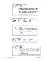
identifies the drive letter assigned to each physical device, and
indicates in bold lettering the device booted from in each configuration, using
devices that are bootable. A bootable device is one on which an operating system
has been installed, or formatted as a system disk using MS-DOS.
3.3.2 Functionality
The CompactFlash performs identically to a standard IDE hard drive. Reads and
writes to the device are performed using the same methods, utilizing DOS
command line entries or the file managers resident in the chosen operating
system.
Advanced Configuration
The previous discussion is based on using the IDE disk devices formatted as one
large partition per device. Some applications may require the use of multiple
partitions. The following discussion of these partitions includes special
procedures that must be followed to create multiple partitions on the CPCI-7806/
CPCI-7806RC IDE disk devices (including the resident CompactFlash).
Partitions may be either a primary or an extended partition. An extended
partition may be subdivided farther into logical partitions. Each device may have
up to four main partitions; one of which may be an extended partition. However,
if multiple primary partitions are created, only one partition may be active at a
time. Data in the non-active partitions are not bootable.
Following the creation of the partitioning scheme, the partitions can be formatted
to contain the desired file system.
As discussed earlier, a typical system consists of the CPCI-7806/CPCI-7806RC
with its resident CompactFlash configured as the Secondary IDE device, a hard
drive attached to the Primary IDE interface, and a floppy drive attached to the
floppy interface.
C:
C:
C:
A:
A:
A:
N/A
N/A
N/A
C:
C:
D:
D:
D:
C:
A:
A:
A:
N/A
N/A
N/A
C:
C:
C:
A:
A:
A:
Primary Only
Secondary Only
Primary and Secondary
PCI IDE Interface Enabled
Floppy Drive
Hard Drive
CompactFlash
A: C: SCSI
C: A: SCSI
CompactFlash
Selected
"Boot Sequence"