


Publication No. 500-657806-000 Rev. G
Embedded PC/RTOS Features 45
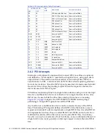
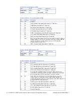
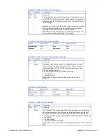
1:0
R/W
WDT_INT_TYPE: The WDT timer supports programmable routing of interrupts. The
set of bits allows the user to choose the type of interrupt desired when the WDT
reached the end of the first stage without being reset.
00 = IRQ* (APIC 1, INT 10
**
) (Default)
01 = Reserved
10 = SMI
11 = Disabled
*IRQ is Active low.
**For operating systems that do not support APIC 1 - the Watchdog Timer Interrupt will be mapped to PIC
Interrupt 9.
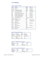
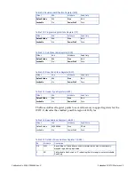
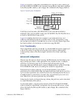
Table 3-20 WDT Lock Register
Offset
68h
Attribute
Read-Write/Write Once
Default Value
00h
Size
8 bit
Lockable
No
Power Well
Core
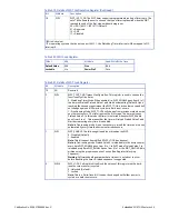
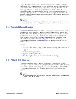
Table 3-21 Details of WDT Lock Register
Bit
Attribute
Description
7:3
RO
Reserved
2
R/W
WDT_TOUT_CNF: Timeout Configuration: This register is used to choose the
functionality of the timer.
0 - Watchdog Timer Mode: When enabled (i.e. WDT_ENABLE goes from 0 to 1)
the timer will reload Preload Value 1 and start decrementing (Default). Upon
reaching the second stage timeout the WDT_TOU# is driven low once and will
not change again until Power is cycled or a hard reset occurs.
1 - Free Running Mode: WDT_TOUT# will change from previous state when the
next timeout occurs. The timer ignores the first stage. The timer only uses
Preload Value 2. In this mode the timer is restarted whenever WDT_Enable
goes from 0 to a 1. This means that the timer will reload Preload Value 2 and
start decrementing every time it is enabled.
Note:
In free running mode it is not necessary to reload the timer as it is done
automatically every time the decrementer reaches zero.
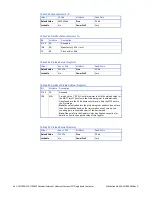
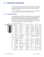
1
R/W
WDT_ENABLE: The following bit enables or disables the WDT.
0 - Disabled (Default)
1 - Enabled
Note:
This bit cannot be modified if WDT_LOCK has been set.
Note:
In free-running mode Preload Value 2 is reloaded into the down counter
every time WDT_ENABLE goes from 0 to 1. In WDT mode Preload Value 1 is
reloaded every time WDT_ENABLE goes from 0 to 1 or the WDT_RELOAD bit is
written using the proper sequence of writes (See Register Unlocking
Sequence).
Warning:
Software should guarantee that a timeout is not about to occur
before disabling the timer. A reload sequence is suggested.
0
R/W0
WDT_LOCK: Setting this bit will lock the values of this register until a hard-
reset occurs or power is cycled.
0 - Unlocked (Default)
1 - Locked
Note:
This is a Write-Once bit. It cannot be changed until either power is
cycled or a hard-reset occurs.
Table 3-19 Details of WDT Configuration Register (Continued)
Bit
Attribute
Description