216
C
HAPTER
16: C
ONFIGURING
LAPB
AND
X.25
Figure 65
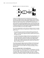
Diagram of X.25 network load balancing
As shown in the above figure, Server A and Server B concurrently provide
subscribers with identical services. They are configured as a hunt group named
hg1. Server A and Server B have the same address of 9999 and the hunt group
address is 8888. Enable the function of destination address substitution on Router
RouterA for changing calls connected to address 8888 to calls connected to
address 9999. When a subscriber processes a service, the subscriber terminal will
send a call to the destination address 8888. The calls from various terminals will be
substituted on the router RouterA with the calls to 9999 and transmitted to Server
A and Server B respectively. Thus load balancing is realized between Server A and
Server B, and the pressure on a single server is decreased.
X.25 hunt group supports two types of call channel selection policies: round-robin
mode and vc-number mode, but a hunt group can only utilize one type of channel
selection policy.
■
In round-robin mode, cyclic selection method is adopted to select the next
interface or the XOT Tunnel for every call request. For example, as shown in
Figure1-1, if hunt group hg1 adopts rotary mode, calls will be sent to Server A
and Server B by turns.
■
vc-number mode selects the interfaces with the free logical channels in a hunt
group for every call request. For example, as shown in the above Figure1-1, if
hunt group hg1 adopts vc-number mode, there will be 500 residual logical
channels in the lines between Server A and DCE and 300 residual logical
channels in the lines between Server B and DCE. Thus all the first 200 calls will
be sent to Server A, and the calls following the first 200 ones will be sent to
Server A and Server B by turns.
X.25 hunt group supports synchronous serial interfaces and XOT Tunnels. It can
indiscriminately select the available lines between synchronous serial interfaces
and XOT Tunnels. But XOT Tunnels cannot calculate the number of logical
channels, therefore it cannot be added into a hunt group adopting vc-number
selection policy.
List of Configuration Tasks of X.25 Load Balancing
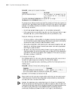
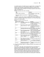
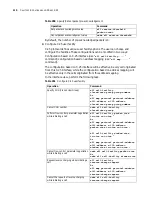
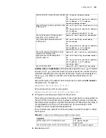
The load balancing of X.25 networks is configured on DCE equipment. The 3Com
Router is generally utilized as a DTE equipment in X.25 networks. If load balancing
is provided by ISPs on packet switching exchanges, routers need no special
configuration. The specific configuration procedure can be seen in the previous
chapters. If the 3Com Router is used as an X.25 switching exchange (it serves as a
X.25
packet
switching
network
User terminal
Server A
Server B
Hunt group HG1
8888
User terminal
User terminal
Remote
DCE
9999
9999
QuidwayA
RouterA
Содержание 3036
Страница 1: ...http www 3com com 3Com Router Configuration Guide Published March 2004 Part No 10014299 ...
Страница 4: ...VPN 615 RELIABILITY 665 QOS 681 DIAL UP 721 ...
Страница 6: ...2 ABOUT THIS GUIDE ...
Страница 7: ...I GETTING STARTED Chapter 1 3Com Router Introduction Chapter 2 3Com Router User Interface ...
Страница 8: ...4 ...
Страница 16: ...12 CHAPTER 1 3COM ROUTER INTRODUCTION ...
Страница 34: ...30 ...
Страница 60: ...56 CHAPTER 3 SYSTEM MANAGEMENT ...
Страница 88: ...84 CHAPTER 5 CONFIGURING NETWORK MANAGEMENT RouterA interface ethernet 0 RouterA Ethernet0 rmon promiscuous ...
Страница 98: ...94 CHAPTER 6 DISPLAY AND DEBUGGING TOOLS ...
Страница 110: ...106 ...
Страница 114: ...110 CHAPTER 8 INTERFACE CONFIGURATION OVERVIEW ...
Страница 158: ...154 CHAPTER 10 CONFIGURING WAN INTERFACE ...
Страница 168: ...164 ...
Страница 188: ...184 CHAPTER 13 CONFIGURING PPPOE CLIENT ...
Страница 192: ...188 CHAPTER 14 CONFIGURING SLIP Router ip route static 0 0 0 0 0 0 0 0 10 110 0 1 ...
Страница 248: ...244 CHAPTER 16 CONFIGURING LAPB AND X 25 ...
Страница 292: ...288 CHAPTER 18 CONFIGURING HDLC Enable HDLC packet debugging debugging hdlc packet interface type number ...
Страница 320: ...316 ...
Страница 330: ...326 CHAPTER 20 CONFIGURING IP ADDRESS ...
Страница 362: ...358 CHAPTER 21 CONFIGURING IP APPLICATION ...
Страница 374: ...370 CHAPTER 23 CONFIGURING IP COUNT ...
Страница 406: ...402 CHAPTER 25 CONFIGURING DLSW ...
Страница 408: ...404 ...
Страница 452: ...448 CHAPTER 29 CONFIGURING OSPF ...
Страница 482: ...478 CHAPTER 30 CONFIGURING BGP ...
Страница 494: ...490 CHAPTER 31 CONFIGURING IP ROUTING POLICY ...
Страница 502: ...498 ...
Страница 508: ...504 CHAPTER 33 IP MULTICAST ...
Страница 514: ...510 CHAPTER 34 CONFIGURING IGMP ...
Страница 526: ...522 CHAPTER 36 CONFIGURING PIM SM ...
Страница 528: ...524 ...
Страница 532: ...528 CHAPTER 37 CONFIGURING TERMINAL ACCESS SECURITY ...
Страница 550: ...546 CHAPTER 38 CONFIGURING AAA AND RADIUS PROTOCOL ...
Страница 590: ...586 CHAPTER 40 CONFIGURING IPSEC ...
Страница 599: ...IX VPN Chapter 42 Configuring VPN Chapter 43 Configuring L2TP Chapter 44 Configuring GRE ...
Страница 600: ...596 ...
Страница 638: ...634 CHAPTER 43 CONFIGURING L2TP ...
Страница 649: ...X RELIABILITY Chapter 45 Configuring a Standby Center Chapter 46 Configuring VRRP ...
Страница 650: ...646 ...
Страница 666: ...662 ...
Страница 670: ...666 CHAPTER 47 QOS OVERVIEW ...
Страница 700: ...696 CHAPTER 49 CONGESTION MANAGEMENT ...
Страница 706: ...702 CHAPTER 50 CONGESTION AVOIDANCE ...
Страница 707: ...XII DIAL UP Chapter 51 Configuring DCC Chapter 52 Configuring Modem ...
Страница 708: ...704 ...
Страница 762: ...758 CHAPTER 52 CONFIGURING MODEM ...

