Configure Frame Relay over Other Protocols
271
■
The DCE device identifies the calling number of the incoming call and
authenticates the DTE device according to it to determine whether to accept or
deny the call.
■
If the DTE device passes the authentication, it can establish a B channel to the
DCE device for carrying out the Frame Relay communications.
Normally, if a DCE device is connected to multiple DTE devices, calls can only be
originated from the DTE side. However, it is not the case for back-to-back
connections.
Binding of multiple B channels is not supported. After a call is successfully made, a
DTE device and a DCE device can only be connected via a B channel.
Since a B channel can only be connected to a remote end and cannot have more
than one IP addresses, it cannot be configured with multiple DLCIs, nor configured
with multiple sub-interfaces.
Physical Connection Between Frame Relay over ISDN Devices
■
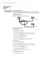
Back-to-back connection between DTE and DCE devices
The DTE and DCE devices are connected to ISDN via ISDN (BRI or PRI)
interfaces, and both ends can make calls, as shown in the following figure:
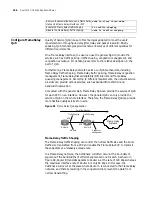
Figure 90
Back-to-back connection between DTE and DCE devices
If legacy BDR is adopted on the ISDN interface used with Frame Relay, the
calling party can directly use the configured dial string to make an ISDN call to
the remote end, after it finds an available B channel. If dialer profiles are
adopted, the calling party will re-configure the selected available B channel
with the link layer protocol on the dialer interface, and then use the configured
dial string to place an ISDN call to the remote end.
After a physical B channel is set up, Frame Relay LMI (Local Management
Interface) and inverse ARP process will start. If an agreement is reached
through the negotiation, Frame Relay will be used to carry the network layer
data on the B channel.
If dialer profiles are adopted, the called party searches for the dialer interface
according to the dialing number in the ISDN packet. If the dialer interface is found,
the called party will re-configure the selected B channel with the link layer
protocol on the dialer interface. If the dialer interface is not found but the
dialer
call-in
command has been configured, it will disconnect the call. If the
dialer
call-in
command is not configured, PPP will be adopted by default. Therefore,
each dialer interface of the called party should be configured with a unique dialing
number, and can only receive the calls from that number. This restriction, however,
is not placed on the calling parties.
■
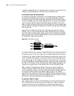
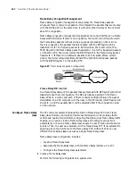
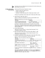
Frame Relay switching connection between DTE devices
ISDN
Switch
Router B
Router A
DTE
DCE
Bri0
Bri1
Pri
Содержание 3036
Страница 1: ...http www 3com com 3Com Router Configuration Guide Published March 2004 Part No 10014299 ...
Страница 4: ...VPN 615 RELIABILITY 665 QOS 681 DIAL UP 721 ...
Страница 6: ...2 ABOUT THIS GUIDE ...
Страница 7: ...I GETTING STARTED Chapter 1 3Com Router Introduction Chapter 2 3Com Router User Interface ...
Страница 8: ...4 ...
Страница 16: ...12 CHAPTER 1 3COM ROUTER INTRODUCTION ...
Страница 34: ...30 ...
Страница 60: ...56 CHAPTER 3 SYSTEM MANAGEMENT ...
Страница 88: ...84 CHAPTER 5 CONFIGURING NETWORK MANAGEMENT RouterA interface ethernet 0 RouterA Ethernet0 rmon promiscuous ...
Страница 98: ...94 CHAPTER 6 DISPLAY AND DEBUGGING TOOLS ...
Страница 110: ...106 ...
Страница 114: ...110 CHAPTER 8 INTERFACE CONFIGURATION OVERVIEW ...
Страница 158: ...154 CHAPTER 10 CONFIGURING WAN INTERFACE ...
Страница 168: ...164 ...
Страница 188: ...184 CHAPTER 13 CONFIGURING PPPOE CLIENT ...
Страница 192: ...188 CHAPTER 14 CONFIGURING SLIP Router ip route static 0 0 0 0 0 0 0 0 10 110 0 1 ...
Страница 248: ...244 CHAPTER 16 CONFIGURING LAPB AND X 25 ...
Страница 292: ...288 CHAPTER 18 CONFIGURING HDLC Enable HDLC packet debugging debugging hdlc packet interface type number ...
Страница 320: ...316 ...
Страница 330: ...326 CHAPTER 20 CONFIGURING IP ADDRESS ...
Страница 362: ...358 CHAPTER 21 CONFIGURING IP APPLICATION ...
Страница 374: ...370 CHAPTER 23 CONFIGURING IP COUNT ...
Страница 406: ...402 CHAPTER 25 CONFIGURING DLSW ...
Страница 408: ...404 ...
Страница 452: ...448 CHAPTER 29 CONFIGURING OSPF ...
Страница 482: ...478 CHAPTER 30 CONFIGURING BGP ...
Страница 494: ...490 CHAPTER 31 CONFIGURING IP ROUTING POLICY ...
Страница 502: ...498 ...
Страница 508: ...504 CHAPTER 33 IP MULTICAST ...
Страница 514: ...510 CHAPTER 34 CONFIGURING IGMP ...
Страница 526: ...522 CHAPTER 36 CONFIGURING PIM SM ...
Страница 528: ...524 ...
Страница 532: ...528 CHAPTER 37 CONFIGURING TERMINAL ACCESS SECURITY ...
Страница 550: ...546 CHAPTER 38 CONFIGURING AAA AND RADIUS PROTOCOL ...
Страница 590: ...586 CHAPTER 40 CONFIGURING IPSEC ...
Страница 599: ...IX VPN Chapter 42 Configuring VPN Chapter 43 Configuring L2TP Chapter 44 Configuring GRE ...
Страница 600: ...596 ...
Страница 638: ...634 CHAPTER 43 CONFIGURING L2TP ...
Страница 649: ...X RELIABILITY Chapter 45 Configuring a Standby Center Chapter 46 Configuring VRRP ...
Страница 650: ...646 ...
Страница 666: ...662 ...
Страница 670: ...666 CHAPTER 47 QOS OVERVIEW ...
Страница 700: ...696 CHAPTER 49 CONGESTION MANAGEMENT ...
Страница 706: ...702 CHAPTER 50 CONGESTION AVOIDANCE ...
Страница 707: ...XII DIAL UP Chapter 51 Configuring DCC Chapter 52 Configuring Modem ...
Страница 708: ...704 ...
Страница 762: ...758 CHAPTER 52 CONFIGURING MODEM ...


