Configure Frame Relay
251
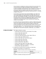
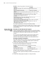
The map created through the dynamic inverse ARP has broadcast attribute.
6
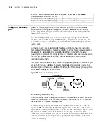
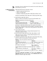
Configure Frame Relay Local Virtual Circuit Number
Perform the following configurations in synchronous serial interface view.
Table 281
Configure Frame Relay local virtual circuit number
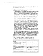
After entering the DLCI view through the
fr dlci
command, the user can
configure the parameters associated with this virtual circuit, such as Frame Relay
class.
The virtual circuit number is valid locally, that is, the virtual circuit numbers on both
ends of the link can be the same. Different interfaces can be assigned with the
same virtual circuit number, but the virtual circuit number must be unique on one
physical interface.
When the Frame Relay interface type is DCE or NNI, the interface (either main
interface or sub-interface) should be configured manully with virtual circuits.
When the Frame Relay interface type is DTE, for the main interface, the system will
determine the virtual circuit automatically according to the opposite equipment;
the sub-interface must be configured with virtual circuits manually.
7
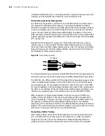
Configure Frame Relay Sub-Interface
The Frame Relay interface is a kind of NBMA (Non-Broadcast Multi-Access)
interface, which supports sub-interfaces. The Frame Relay module has two types
of interfaces: main interface and sub-interface. The sub-interface is logical
interface and can be used to configure protocol address and virtual circuit. One
physical interface can include multiple sub-interfaces, which do not exist
physically. However, for the network layer, both the sub-interface and main
interface can be used to configure the virtual circuit to connect to remote
equipment.
The sub-interfaces of Frame Relay fall into two types: point-to-point sub-interface,
used to connect a single remote object and point-to-multipoint sub-interface,
used to connect multiple remote objects in the same network segment.
The address mapping relation between the frame-relay sub-interfaces can be
configured manually, or dynamically established by using the inverse ARP. For a
point-to-point sub-interface, you only need configure one PVC on this
sub-interface, since there is only one peer device. For a point-to-multipoint
sub-interface, you can configure multiple PVCs. Each PVC can establish the
address mapping with its connected peer through running the inverse dynamic
ARP. Thereby, different PVCs can reach their peers without confusing.
Alternatively, you can respectively establish different static address mapping for
these PVCs.
a
Creating Frame Relay Sub-Interface
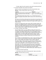
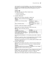
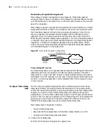
In the interface view, perform the following task to create a sub-interface.
Table 282
Create Frame Relay sub-interface
Operation
Command
Assign a virtual circuit number to Frame Relay interface
fr dlci
dlci-number
Remove the virtual circuit number of Frame Relay
interface
undo fr dlci
dlci-number
Operation
Command
Enter interface view
interface
type
number
Содержание 3036
Страница 1: ...http www 3com com 3Com Router Configuration Guide Published March 2004 Part No 10014299 ...
Страница 4: ...VPN 615 RELIABILITY 665 QOS 681 DIAL UP 721 ...
Страница 6: ...2 ABOUT THIS GUIDE ...
Страница 7: ...I GETTING STARTED Chapter 1 3Com Router Introduction Chapter 2 3Com Router User Interface ...
Страница 8: ...4 ...
Страница 16: ...12 CHAPTER 1 3COM ROUTER INTRODUCTION ...
Страница 34: ...30 ...
Страница 60: ...56 CHAPTER 3 SYSTEM MANAGEMENT ...
Страница 88: ...84 CHAPTER 5 CONFIGURING NETWORK MANAGEMENT RouterA interface ethernet 0 RouterA Ethernet0 rmon promiscuous ...
Страница 98: ...94 CHAPTER 6 DISPLAY AND DEBUGGING TOOLS ...
Страница 110: ...106 ...
Страница 114: ...110 CHAPTER 8 INTERFACE CONFIGURATION OVERVIEW ...
Страница 158: ...154 CHAPTER 10 CONFIGURING WAN INTERFACE ...
Страница 168: ...164 ...
Страница 188: ...184 CHAPTER 13 CONFIGURING PPPOE CLIENT ...
Страница 192: ...188 CHAPTER 14 CONFIGURING SLIP Router ip route static 0 0 0 0 0 0 0 0 10 110 0 1 ...
Страница 248: ...244 CHAPTER 16 CONFIGURING LAPB AND X 25 ...
Страница 292: ...288 CHAPTER 18 CONFIGURING HDLC Enable HDLC packet debugging debugging hdlc packet interface type number ...
Страница 320: ...316 ...
Страница 330: ...326 CHAPTER 20 CONFIGURING IP ADDRESS ...
Страница 362: ...358 CHAPTER 21 CONFIGURING IP APPLICATION ...
Страница 374: ...370 CHAPTER 23 CONFIGURING IP COUNT ...
Страница 406: ...402 CHAPTER 25 CONFIGURING DLSW ...
Страница 408: ...404 ...
Страница 452: ...448 CHAPTER 29 CONFIGURING OSPF ...
Страница 482: ...478 CHAPTER 30 CONFIGURING BGP ...
Страница 494: ...490 CHAPTER 31 CONFIGURING IP ROUTING POLICY ...
Страница 502: ...498 ...
Страница 508: ...504 CHAPTER 33 IP MULTICAST ...
Страница 514: ...510 CHAPTER 34 CONFIGURING IGMP ...
Страница 526: ...522 CHAPTER 36 CONFIGURING PIM SM ...
Страница 528: ...524 ...
Страница 532: ...528 CHAPTER 37 CONFIGURING TERMINAL ACCESS SECURITY ...
Страница 550: ...546 CHAPTER 38 CONFIGURING AAA AND RADIUS PROTOCOL ...
Страница 590: ...586 CHAPTER 40 CONFIGURING IPSEC ...
Страница 599: ...IX VPN Chapter 42 Configuring VPN Chapter 43 Configuring L2TP Chapter 44 Configuring GRE ...
Страница 600: ...596 ...
Страница 638: ...634 CHAPTER 43 CONFIGURING L2TP ...
Страница 649: ...X RELIABILITY Chapter 45 Configuring a Standby Center Chapter 46 Configuring VRRP ...
Страница 650: ...646 ...
Страница 666: ...662 ...
Страница 670: ...666 CHAPTER 47 QOS OVERVIEW ...
Страница 700: ...696 CHAPTER 49 CONGESTION MANAGEMENT ...
Страница 706: ...702 CHAPTER 50 CONGESTION AVOIDANCE ...
Страница 707: ...XII DIAL UP Chapter 51 Configuring DCC Chapter 52 Configuring Modem ...
Страница 708: ...704 ...
Страница 762: ...758 CHAPTER 52 CONFIGURING MODEM ...


