1-7
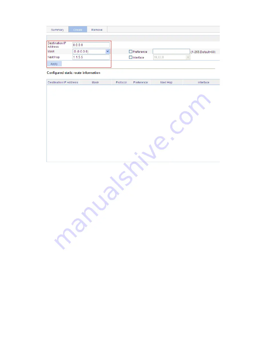
Figure 1-6
Configure a default route
z
Type
0.0.0.0
for
Destination IP Address
.
z
Select
0 (0.0.0.0)
from the
Mask
drop-down list.
z
Type
1.1.5.5
for
Next Hop
.
z
Click
Apply
.
Verify the configuration
# Display the route table.
Enter the IPv4 route page of Switch A, Switch B, and Switch C respectively to verify that the newly
configured static routes are displayed as active routes on the page.
# Use the
ping
command for verification.
Ping Host B from Host A (assuming both hosts run Windows XP).
C:\Documents and Settings\Administrator>ping 1.1.3.2
Pinging 1.1.3.2 with 32 bytes of data:
Reply from 1.1.3.2: bytes=32 time=1ms TTL=128
Reply from 1.1.3.2: bytes=32 time=1ms TTL=128
Reply from 1.1.3.2: bytes=32 time=1ms TTL=128
Reply from 1.1.3.2: bytes=32 time=1ms TTL=128
Ping statistics for 1.1.3.2:
Packets: Sent = 4, Received = 4, Lost = 0 (0% loss),
Содержание 2928 - Baseline Plus Switch PWR
Страница 92: ...1 9 Figure 1 7 Display the rate settings of ports ...
Страница 105: ...1 4 Figure 1 3 Switch to the management level ...
Страница 106: ...i Table of Contents 1 Loopback Test Configuration 1 1 Overview 1 1 Loopback Operation 1 1 Configuration Guidelines 1 2 ...
Страница 109: ...i Table of Contents 1 VCT 1 1 Overview 1 1 Testing Cable Status 1 1 ...
Страница 114: ...1 2 Figure 1 2 Port traffic statistics ...
Страница 138: ...i Table of Contents 1 Energy Saving Configuration 1 1 Overview 1 1 Configuring Energy Saving on a Port 1 1 ...
Страница 159: ...i Table of Contents 1 Interface Statistics 1 1 Overview 1 1 Displaying Interface Statistics 1 1 ...
Страница 279: ...1 28 Figure 1 26 The Port Setup tab ...
Страница 331: ...i Table of Contents 1 Service Management 1 1 Overview 1 1 Configuring Service Management 1 2 ...


