


ZHDN 2500-150
Installation
21
www.zepro.com
2x M12x100 8.8
80 Nm
2x M12x80 8.8
80 Nm
2x M12x80 8.8
80 Nm
2x M12x100 8.8
80 Nm
6.9
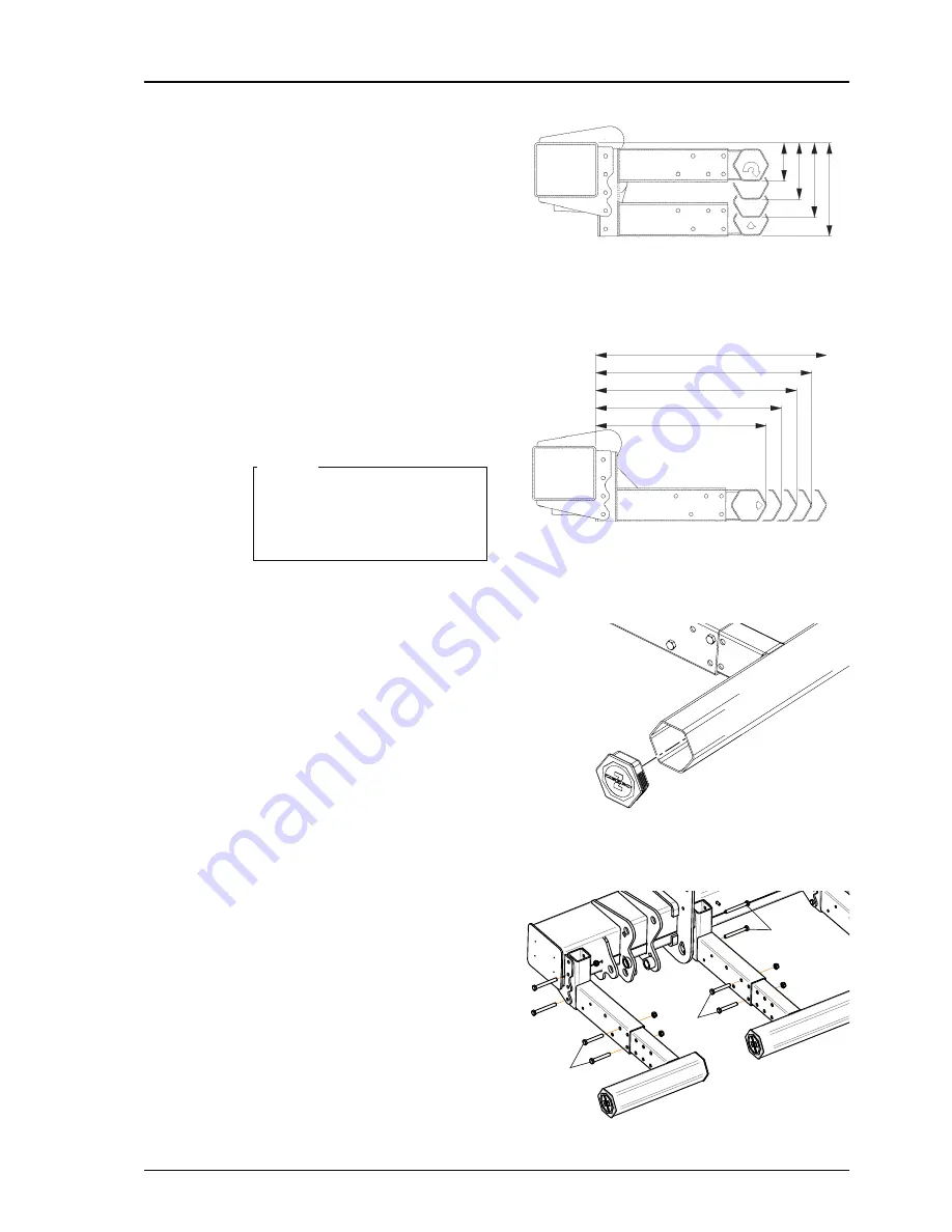
Underrun protection
Test the position of the underrun protection
without tightening the bolts to check that
the statutory dimensions are obtained.
Adjust if necessary then tighten the bolts
with a torque wrench.
1. Fit the inner brackets at one of four
heights. Select the height that meets
the statutory requirements. Use the
correct bolts M12x100. Assemble
without tightening the bolts. See
2.
Fit the outer brackets at one of five
positions. Select the position that
meets the statutory requirements.
Use the correct bolts M12x80. As-
semble without tightening the bolts.
See illustration.
The underrun protection may be
placed further back and lower
than the specified measure-
ments.
NOTE.
3. Check that the installation meets the
statutory requirements.
4. Tighten all the bolts using a torque
wrench.
Tightening torque: 80 Nm.
5. Fit the beam end caps, rotated so the
logo is the right way up, and press
them firmly to secure. If necessary,
tap carefully with a rubber hammer.
Image 22. The inner brackets can be fitted at
one of four heights
Image 23. The outer brackets can be fit-
ted in one of five positions.
Image 24. Fit the beam end caps
Image 25. Installing underrun protection
133
193
241
301
617
667
717
767
817


