PROVERGE SETUP AND ADJUSTMENT
PV152
3-19
PRO1200 PROVERGE SETUP
NOTE: if you had to use the arrow keys
ç
or
è
to adjust
the phase, this means that the phase of the Reference
Source was originally not adjusted correctly. Hence
the Reference Source may now fall short of the
physical screen. To avoid this, re-adjust the
Horizontal Raster Shift (in the Random Access
Adjustment mode, refer to Owner Manual) so that
the Reference Source falls on the physical screen
and repeat the Learn Reference selection.
Do not adjust the phase when repeating the Learn
Reference procedure.
Pressing <EXIT> will interrupt the Learn Reference procedure
if required.
WHAT IS BEING MEASURED BY PROVERGE
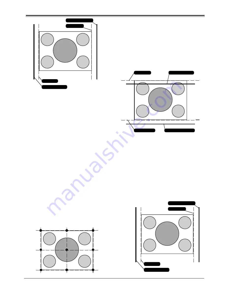
Using the borderlines defined above,
PROVERGE
knows
exactly when the image starts and stops with respect to time
scale.
PROVERGE
is now able to project lines at the edges.
Using the border lines left and right,
PROVERGE
projects
three vertical thick green lines at positions 5, 50 and 95 %.
Using the border lines top and bottom,
PROVERGE
projects
three horizontal thick lines at positions 5, 50 and 95 %.
PROVERGE
then calculates the intercepts of the three
vertical and three horizontal lines resulting in nine points.
These nine points are the reference points for other geometry
sources and are stored into memory.
note:
“delete all blocks” in the Service menu does not delete
the Reference Source parameters.
ADJUSTMENT OF GEOMETRY OF OTHER SOURCES
Follow the steps below to select :
1. Enter into the Adjustment Mode and select
PROVERGE
, by
pushing
é
or
ê
keys of the control disc. Now select FULL
AUTOPICTURE.
2. A ‘Define Image’ screen will be shown stating,”define the
top and bottom border by adjusting the projected line
with
é
or
ê
in order to frame the projected image
horizontally, adjust the projected lines with
é
or
ê
and
correct the phase of the image with
ç
or
è
.” Press
<ENTER> to continue the process, or press <EXIT> to quit.
If continuing
PROVERGE
will project the source with a
horizontal green line inserted at the top and a horizontal
green line inserted at the bottom of the image.
3. Pushing the
é
or
ê
keys of the control disc adjust the
horizontal green line at the top until it matches the top
edge of the image perfectly, then press <ENTER>.
4. Using the
é
or
ê
keys of the control disc adjust the
horizontal green line at the bottom until it matches the
bottom edge of the image perfectly, then press <ENTER>.
Note: Now
PROVERGE projects the source with a vertical
green line inserted at the left and a vertical green
line inserted at the right.
ñ
ñ
Right Edge
Right Green Line
Left Green Line
Left Edge
ñ
ñ
REFERENCE SOURCE
Bottom Edge
Bottom Green Line
Top Green Line
Top Edge
ñ
ñ
ñ
ñ
SELECTED SOURCE
ñ
ñ
Right Edge
Right Green Line
Left Green Line
Left Edge
ñ
ñ
SELECTED SOURCE


