Instruction Manual
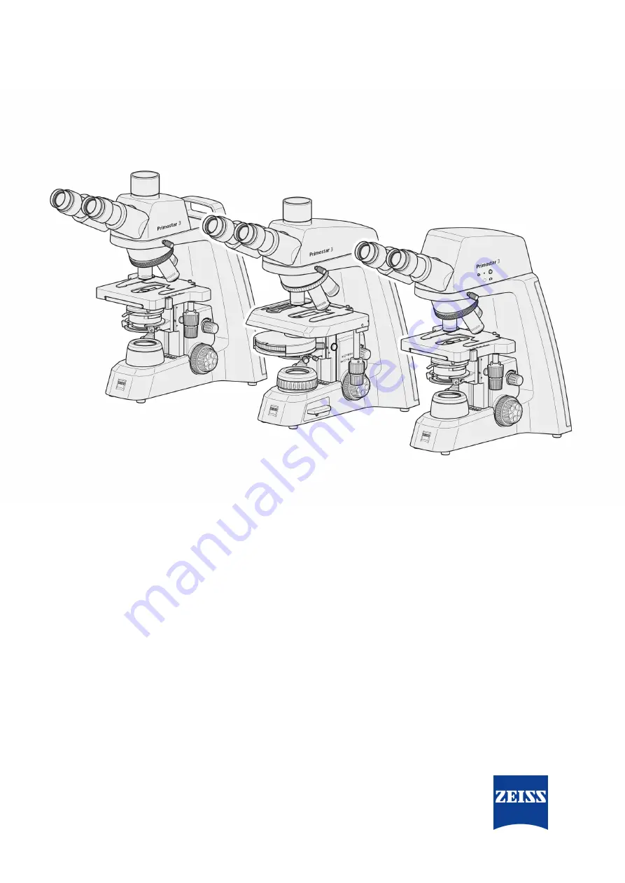
ZEISS Primostar 3
Upright Microscope for Education and Routine
Page 1: ...Instruction Manual ZEISS Primostar 3 Upright Microscope for Education and Routine...
Page 2: ...ackup copies for archiving purposes shall remain unaffected thereby Any viola tions may be prosecuted as copyright infringements The use of general descriptive names registered names trademarks etc in...
Page 3: ...3 2 Controls and Connections 20 3 2 1 Fixed K hler Stand 20 3 2 2 Full K hler Stand 23 3 2 3 Reflected Light Fluorescence Illuminator iLED 26 3 2 4 Primostar 3 HD IP Camera 27 3 2 5 Battery Supply Uni...
Page 4: ...isites for Commissioning and Operation 65 5 2 Switching on the Microscope 65 5 2 1 Microscope is directly connected to the Mains Power Supply 65 5 2 2 Microscope is connected to the External DC Power...
Page 5: ...1 Troubleshooting Primostar 3 HD IP Camera 93 7 1 1 Troubleshooting with ZEN Lite Software 95 8 Transport and Storage 96 8 1 Important Data for Transport and Storage 96 9 Technical Data and Conformit...
Page 6: ...el Air lock Follow a path in the software Text input Text to be entered by the user Programming and Macros Anything typed in literally during program ming including for example macro codes keywords da...
Page 7: ...also note of the following documents Installation Requirements For more details on technical data refer to the corresponding Installation Requirements System and 3rd Party Components Accessories The M...
Page 8: ...39 Email info microscopy de zeiss com Service Germany Phone 49 7364 20 3800 Fax 49 7364 20 3226 Email service microscopy de zeiss com Courses and training Email courses microscopy de zeiss com ZEISS S...
Page 9: ...struction Manual must be read before commissioning to ensure safe and permanent opera tion Pay particular attention to all listed safety notes Please ensure that the operating personnel have read unde...
Page 10: ...he user Only operate the device on a stable work table with a solid and smooth tabletop Risk of burns The microscope emits heat during operation and up to ten minutes after it is switched off Before a...
Page 11: ...mponents lead to the loss of all warranty claims Only use microscope com ponents supplied by ZEISS Do not open the device unless you are trained and explicitly authorized by ZEISS Always contact ZEISS...
Page 12: ...els on the battery supply unit The meaning of each warning and information label is explained below Posi tion Symbol Description 1 Hot surface below Operate microscope only on a stable solid smooth an...
Page 13: ...f battery type switch ON NIMH OFF NiCd Tab 3 List of attached warning and information labels 2 5 Safety Devices and Interlocks In order to prevent injuries and or property damage the Microscope is equ...
Page 14: ...ed off as soon as the reflected light illuminator is turned with regard to the stand or detached Defective and damaged safety devices can lead to injuries and damage In the event of damage or defect t...
Page 15: ...brightfield darkfield simple polarization and phase contrast mi croscopy The Microscope is optionally available with a camera port for photo and video documentation For special camera applications th...
Page 16: ...the Fixed K hler microscope 1 Eyepiece WF 10x 20 Br Foc 2 Nosepiece with four positions 3 Objective 4 Rackless stage 75x40 drive right or drive left 5 Abbe condenser 0 9 1 25 field 20 Fixed K hler 6 C...
Page 17: ...Rackless stage 75x40 drive right or drive left 6 Abbe condenser 0 9 1 25 field 20 Fixed K hler 7 Condenser carrier Fixed K hler 8 Yellow filter inserted with filter position for adapting the color te...
Page 18: ...s of Fixed K hler microscope with Primostar 3 HD IP camera 1 Eyepiece WF 10x 20 Br Foc 2 Nosepiece with four positions 3 Objective 4 Rackless stage 75x40 drive right or drive left 5 Abbe condenser 0 9...
Page 19: ...positions 3 Objective 4 Rackless stage 75x50 drive right or drive left 5 Turret condenser 0 9 1 25 field 22 Full K hler or Abbe condenser 0 9 1 25 field 22 Full K hler 6 Condenser carrier with center...
Page 20: ...n condenser carrier left side 5 Centering screw Allen screw for con denser on condenser carrier right side 6 Cover cap of the luminous field di aphragm 7 Clamping screw for condenser 8 Small hand lift...
Page 21: ...sity is indicated in five layers by the Cyan light emitting diodes belt 2 Clamping screw for the specimen holder 3 Vernier and scale displaying the X posi tion of the stage 4 Lever of the specimen hol...
Page 22: ...arrying handle 2 Holder for power cable 3 Main power ON OFF button 4 5V USB port for mobile power bank 5 Storage place for phase plate adjust ment tool 6 DC 5V switch 7 Mains socket 8 Connection port...
Page 23: ...n condenser carrier right side 5 Cover cap of the luminous field di aphragm 6 Knurled ring for adjusting the luminous field diaphragm 7 Clamping screw for condenser 8 Illumination intensity indicators...
Page 24: ...for the specimen holder 3 Vernier and scale displaying the X posi tion of the stage Knurled ring for condenser height ad justment 4 Vernier and scale displaying the Y posi tion of the stage 5 Lever of...
Page 25: ...change back to objective A light intensity will return to the last setting The light intensity of all five objectives can be remembered The Light Manager feature can be disabled by pushing the intensi...
Page 26: ...reflected light fluorescence illuminator 1 Pilot lamp for reflected light fluores cence illuminator lights up blue when switched on brightness corresponds to intensity 2 Clamping screw for tube 3 Rot...
Page 27: ...ter nal medium such as a separate monitor PC or tablet PC via data line or Wi Fi connection Position The Primostar 3 HD IP camera can only be mounted on the stand without small handle lift 2 3 1 Fig 1...
Page 28: ...drive or the drive is full LED flashes pink Tab 4 System status operating mode of the Primostar 3 HD IP camera shown by LED indicator 2 1 1 Fig 18 Cover plate for covering the USB TYPE A port and the...
Page 29: ...The rechargeable batteries of the battery supply unit provide power to the microscope when mains power is not available Position The battery supply unit is connected via a power supply cable to the ba...
Page 30: ...charge the batteries the unit must be connected to the mains power supply Shortly before automatic disconnection of the rechargeable battery pack ex haustive discharge protection the green power on l...
Page 31: ...on The provided diopter scale helps to find the correct setting When using the microscope with the Reflected Light Fluorescence Illuminator iLED for fluores cence applications the special eyecups with...
Page 32: ...pply HDMI cable can order in demo kit Connection between camera and monitor TV or projector USB flash drive Type A not supplied Connection to camera for immediate image and video storage USB hub Type...
Page 33: ...ics of an objective are indicated by the respective labeling e g iPlan ACHROMAT 10x 0 25 Feature Label Remarks Magnification 10 The objective s magnification factor is also expressed by the objective...
Page 34: ...thickness 0 17 mm Tab 6 Obligatory label components Feature Label Remarks Immersion oil Oil The objective can be used with immersion oil Phase contrast objective Ph The objective can be used in phase...
Page 35: ...button Snaps a single image 3 Record button Starts a video recording A time counter is displayed When pushing the button the following controls expand Enables you to manually re adjust the exposure ti...
Page 36: ...propri ate results When pushing the button the follow ing controls expand The exposure time can be fine tuned using the upper slider or input field The gain value can be set using the lower slider or...
Page 37: ...tings icon Opens the Image Settings menu 2 Microscope System Settings icon Opens the Microscope System Set tings menu 3 Operating System Settings icon Opens the Operating System Settings menu 4 System...
Page 38: ...se button Reduces noise 3 Image Orientation controls Sets the image orientation 0 original image orientation Mirror vertical image mirrored in verti cal direction Mirror horizontal image mirrored in h...
Page 39: ...r stands Opens a drop down list to define the item installed at the objective turret s current position 2 Shading Correction button Opens a menu to define the shading correction for each combination o...
Page 40: ...le Options Menu 41 4 HDMI Resolution button Opens a menu to set the desired HDMI resolution for live view Notes Switching from 1080p to 4K must be confirmed by pressing the Confirm but ton The camera...
Page 41: ...tom fields Empty fields will be removed from the template The date and time format can be set A counter number is appended to each filename by default 3 Set Filename after each Snap button Activates a...
Page 42: ...tical surfaces when unpacking the microscope to avoid fingerprints 4 2 Prepare Installation The microscope is supplied completely assembled and including accessories that are packed to commercial stan...
Page 43: ...ed un der the two holding elements 2 Place the tube horizontally onto the stand The groove on the underside of the tube must be located above the third holding ele ment of the stand 3 Turn the tube co...
Page 44: ...h the tube 4 3 2 Installing the Reflected light Fluorescence Illuminator iLED onto the Stand Prerequisite The microscope is unplugged from mains power Stand without small hand lift RJ12 cable is avail...
Page 45: ...to face backwards with the dovetail mount in the stand 4 Plug the RJ12 cable into the RJ12 female con nector port of the stand 5 Align the reflected light illuminator to the outer edges of the stand 6...
Page 46: ...red place the yellow filter onto the luminous field diaphragm see Attaching or Re moving Yellow Filter or TL Cover Plate Fixed K hler Stand 47 Info Special eyecups with light protection see Changing t...
Page 47: ...the luminous field diaphragm and remove it 2 Place the yellow filter onto the mounting surface of the luminous field diaphragm or re move it if necessary 3 Re attach the cover cap to the luminous fie...
Page 48: ...far as it will go by turning the knurled ring for condenser height adjustment 2 Unscrew the cover cap from the luminous field diaphragm 3 Put the desired filter yellow green or blue onto the mounting...
Page 49: ...minous field diaphragm The position stop on the polarizer plate has to match with the position stop on the lumi nous field diaphragm 4 3 6 Installing the Analyzer Plate Prerequisite The microscope is...
Page 50: ...ight Fluorescence Illuminator iLED onto the Stand 44 Then mount the Primostar 3 HD IP camera onto the reflected light fluorescence illuminator iLED in the same way as described below Procedure 1 Remov...
Page 51: ...12 female con nector port of the stand If the reflected light fluorescence illuminator iLED is used plug the RJ12 cable into the upper RJ12 female connector port of the reflected light fluorescence il...
Page 52: ...sure the RJ12 cable is invisible 4 3 8 Installing a Camera to the Trinocular Tube Prerequisite A trinocular tube photo tube is mounted on the microscope A camera adapter P95 C 2 3 0 65x or P95 C 1 2 0...
Page 53: ...ng Objectives Procedure 1 Turn the focusing drive to move the mechanical stage down as far as it will go 2 Turn the nosepiece to move the objective to be changed into a lateral position 3 Unscrew the...
Page 54: ...er the condenser carrier as far as it will go using the knurled screw for vertical adjustment 3 Loosen the clamping screw of the condenser so that the condenser can be removed front ward Use an Allen...
Page 55: ...the condenser carrier insert backward against the spring and inclining it remove it upward from the condenser carrier 5 Insert the mirror from the top through the opening of the condenser carrier and...
Page 56: ...screw the stop from the eyepiece by hand 4 Insert the eyepiece pointer or the eyepiece mi crometer into the eyepiece with the coated side facing your eyes 5 Screw in the eyepiece stop again 6 Insert t...
Page 57: ...he Eyecups Procedure 1 If required fold over the rubber eyecups 4 3 14 Changing the Eyecups Procedure 1 Remove the existing eyecup from the eyepiece e g the foldover rubber eyecups 2 Attach the desire...
Page 58: ...OUT position The DC 5V switch is only available on Fixed K hler stands 3 Plug the other end 5 of the power cable into the mains power supply 4 4 4 2 Connecting the Microscope to the Battery Supply Un...
Page 59: ...ands can be connected to a power bank for power supply Prerequisite The microscope is installed completely with all components to be used The mobile power bank is charged Procedure 1 Plug the USB Type...
Page 60: ...e into one of the USB Type A ports of the Primostar 3 HD IP camera Info To view the captured images or videos connect the USB flash drive to a PC or laptop 4 5 2 Connecting to the PC via USB 3 0 Port...
Page 61: ...ack of the monitor projector 3 Set the display device s aspect ratio to 16 9 or Aspect 4 5 4 Integrating the Primostar 3 HD IP Camera into a Network The Primostar 3 HD IP camera is able to communicate...
Page 62: ...rnet cable into the jack on the reverse side of the Primostar 3 HD IP camera 2 Insert the Ethernet cable s opposite connector into the corresponding socket on your WLAN router 3 Switch on the router L...
Page 63: ...s MAC address label is on top of the Primostar 3 HD IP camera for example Primostar3_F9A919 Password ZEISS1846 Info When a compatible USB Wi Fi adapter is inserted into the Primostar 3 HD IP camera tu...
Page 64: ...stalling the Labscope Software on PC Prerequisite WINDOWS PC is required Procedure 1 Go to www zeiss com labscope for free download 2 Install the Labscope App as described 4 6 2 Installing the ZEISS Z...
Page 65: ...ning and keep the manual for further use Basic training and safety briefing successfully completed Chapter Safety read and understood Familiar with general Windows based programs 5 2 Switching on the...
Page 66: ...completely installed The battery supply unit is charged and connected to the microscope Procedure 1 Ensure the DC 5V switch is in the OUT posi tion 2 Switch on the battery supply unit 3 Switch on the...
Page 67: ...n comprises several individual action sequences Prerequisite The microscope is connected to the mains and is switched on Procedure 1 Setting the Interpupillary Distance 67 2 Setting the Viewing Height...
Page 68: ...the tube and fix it with the set screw 2 Turn the focusing ring of the eyepiece to focus on the wedge shaped figure of the eyepiece pointer 3 Put the specimen onto the mechanical stage 4 Look at the s...
Page 69: ...sting the Transmitted Light Brightfield on the Full K hler Microscope Parts and Tools High contrast specimen slide with cover glass of 0 17 mm thickness Info The knurled knob for the vertical condense...
Page 70: ...the light path 4 If the microscope stand is equipped with the turret condenser move turret to BF position 5 When using the Reflected light Fluorescence Il luminator iLED turn the transmitted light re...
Page 71: ...o set the aperture diaphragm to the middle position 9 Look through one eyepiece and use the focus ing drive to bring the specimen into focus 10 If necessary readjust the image sharpness for the other...
Page 72: ...ce from the tube and look through the tube 16 Use the control lever of the aperture diaphragm to adjust the aperture diaphragm to ap proximately 2 3 to 4 5 of the diameter of the exit pupil of the obj...
Page 73: ...n holder of the mechanical stage 2 If the microscope stand is equipped with a dark field slider pull this slider to the left up to the lock in position 3 When using the Reflected light Fluorescence Il...
Page 74: ...ation to a comfortable setting If the condenser has been removed e g for installing the illuminating mirror make sure to rein stall and center it using the two centering screws see Installing Removing...
Page 75: ...2 Turn the nosepiece to move the phase contrast objective Ph 2 into the light path 3 Open the luminous field diaphragm on the stand 4 Remove the dummy slider from the Abbe con denser 5 Remove the lock...
Page 76: ...center the phase stop remove one eyepiece and replace it with the diopter or telescope 10 If it is necessary to center the phase stop insert the two Allen wrenches into the adjusting screws of the ph...
Page 77: ...smitted Light Phase Contrast or the Transmitted Light Darkfield using a Contrast Slider Info For darkfield application use the darkfield slider instead of the phase contrast slider Instruction Manual...
Page 78: ...phase contrast stop or darkfield stop inserted is required Procedure 1 Adjust the microscope as you would for transmitted light brightfield see Adjusting the Transmitted Light Brightfield on the Full...
Page 79: ...er or telescope 8 If necessary center the phase stop from posi tion A to position B by turning the two adjusting screws in the adjustment holes using two Allen wrenches A B 9 Afterwards replace the di...
Page 80: ...would for transmitted light brightfield see Adjusting the Transmitted Light Brightfield on the Full K hler Microscope 69 2 Place the specimen to be examined under po larized light on the stage and fix...
Page 81: ...ight LED using the ro tary knob of the reflected light illuminator and adjust the illumination intensity to a level com fortable for observation The pilot lamp at the front of the reflected light illu...
Page 82: ...nations in rooms which are not darkened They are however not suitable for spectacle wearers and must not be folded over because the required dimensional stability would be lost 5 10 Capturing Images a...
Page 83: ...ideo recording click on Stop in the OSD menu The video is saved to the USB flash drive in MP4 format 5 10 3 Image Capture with Labscope or ZEN Lite Prerequisite Wi Fi adapter is inserted into the spec...
Page 84: ...tching off the Microscope Procedure 1 After finishing work switch off the microscope at the main power ON OFF button 2 If connected switch off the power bank 3 Cover the microscope with the dust cover...
Page 85: ...oltage hazard in case of contact with live parts Risk of burns and electrocution 4 Switch off microscope prior to opening and cleaning 4 Disconnect live parts from the power supply 6 2 Maintenance Sch...
Page 86: ...se serious injuries or death 4 Before changing the halogen lamp switch off the device 4 Unplug the microscope from mains power supply CAUTION Risk of burns The halogen lamp emits heat to an extent tha...
Page 87: ...r supply 4 Insert rechargeable batteries only 4 Use only batteries of the same type and capacity as specified see Technical Data and Con formity 4 Make sure that the battery type switch is in the corr...
Page 88: ...ure 1 Connect the battery supply unit to the mains power supply using the plug in power unit The green power on light Ready is on The batteries are charged automatically The yellow charge indicator li...
Page 89: ...ection cover if the Microscope is not used 4 The ventilation slots must be unobstructed at all times 4 Perform regular maintenance and cleaning according to the instructions in this document and accor...
Page 90: ...ng to the edges using light pressure only 8 Make sure that no moisture gets into the microscope the plug in power unit or the battery supply unit 9 For use in warm and humid climates all optical compo...
Page 91: ...d light objectives corrected for 0 17 mm cover glass Use standard 0 17 mm cover glass Use of no or non specified im mersion oil with immersion objective Use the supplied immersion oil Air bubbles in i...
Page 92: ...t be switched on Transmitted light reflected light changeover switch is in reflected light Fluorescence position Turn transmitted light re flected light changeover switch to transmitted light Brightfi...
Page 93: ...drive is not rec ognized or the firmware is not uploaded properly Insert a FAT32 formatted USB flash drive with latest firmware in the root folder and make sure the drive has at least 200 MB free mem...
Page 94: ...e is blurred on the screen but the sample is in focus through eye pieces Focus plane of the camera is different from that of the eye pieces Make sure the sample is fo cused correctly through eye piece...
Page 95: ...ust the USB 3 0 connections to PC and power supply if necessary Ensure that the software has been installed with administra tive rights and according to the instructions in this manual Connect the Pri...
Page 96: ...le components that can be assembled and disassembled separately 8 1 Important Data for Transport and Storage Storage in packaging Parameter Value Permissible ambient temperature 40 to 70 C Permissible...
Page 97: ...sources cannot interfere with image acquisition The Microscope should not be installed near windows with direct sunlight or radiators Compliance with the installation requirements of the Microscope a...
Page 98: ...r day regardless of whether the microscope is in operation or switched off 5 to 40 C Relative humidity 80 at 40 C Atmospheric pressure 800 hPa to 1060 hPa Pollution degree 2 Mains connection Parameter...
Page 99: ...K Luminous flux 280 lm Average service life 1000 h Luminous area 1 5 x 3 mm LED illumination Feature Value LED white light Constant brightness independent color tem perature 5600 K Homogeneous field...
Page 100: ...s readable from the right Specimen holder with spring lever left Condenser Feature Value Abbe condenser 0 9 1 25 Fixed K hler for Vobj 4x to 100x Abbe condenser 0 9 1 25 Full K hler for Vobj 4x to 100...
Page 101: ...view number 22 Interpupillary distance adjustable from 48 to 75 mm Tube angle 25 Viewing height 380 to 415 mm Viewing port tube factor 1x Photo video port tube factor 1x Photo video port mount 60 mm I...
Page 102: ...umina tion Number of pixels 3840 H x 2160 V 8 3 megapixels Pixel size 1 85 x 1 85 m Sensor size image diagonal 8 15 mm equivalent to 1 1 9 Live image frame rate via HDMI 3840 x 2160 30 fps maximal val...
Page 103: ...iLED in Fixed K hler design Full K hler or Fixed K hler Abbe condenser turret condenser for brightfield darkfield polarization and phase contrast for Full K hler design only Convenient coaxial coarse...
Page 104: ...1631 000 Objective iPAcr 100x 1 25 Oil D 0 415501 1642 000 Objectives and accessories for phase contrast Component Cat No Objective iPAcr 10x 0 25 Ph1 415501 1615 000 Objective iPAcr 20x 0 45 Ph2 415...
Page 105: ...et condenser with BF Ph1 Ph2 Ph3 DF 415501 1700 000 Specimen holders Component Cat No Specimen holder lh 415501 1304 000 Specimen holder work f two slides lh 415501 1305 000 External components Compon...
Page 106: ...ra adapter P95 C 2 3 0 65x 415501 1810 000 Camera adapter P95 C 1 2 0 5x 415501 1811 000 Immersion media and accessories Component Cat No Immersion oil Immersol 518 N oiler 20 ml 000000 1111 806 Immer...
Page 107: ...s and special components on the rear side of the reflected light fluo rescence illuminator 27 Fig 17 Controls of the Primostar 3 HD IP camera 27 Fig 18 Cover plate for covering the USB TYPE A port and...
Page 108: ...or 28 Tab 5 Connecting cables and accessories 32 Tab 6 Obligatory label components 33 Tab 7 Further label components 34 Tab 8 Maintenance Plan 85 Tab 9 Auxiliary materials required for care 89 Tab 10...
Page 109: ...ance of the microscope particularly that of the objective the condenser luminous field diaphragm and aperture diaphragm should be set based on the rules of the K HLER illumination principle USB Univer...
Page 110: ...er stand 24 Primostar 3 HD IP camera 27 Reflected light fluorescence illuminator 26 D Darkfield 75 78 E EMC requirements 98 Ethernet 62 Eyecup 57 Eyepiece 31 Eyepiece micrometer 68 Eyepiece pointer 55...
Page 111: ...uirements for users 10 S Safe Operating Condition 9 Safety 9 devices 13 14 General 9 interlocks 13 Settings menu 37 Software 7 64 Standards 97 Storage 96 Switching off 84 Switching on 65 66 67 T Tool...
Page 112: ...rl Zeiss Promenade 10 07745 Jena Germany phone 49 1803 33 63 34 fax 49 3641 64 3439 info microscopy de zeiss com www zeiss com microscopy Instruction Manual ZEISS Primostar 3 en US Rev 1 Modifications...