AF9ZP0BA - EPS-ACW REACH TRUCK - User Manual
Page - 23/90
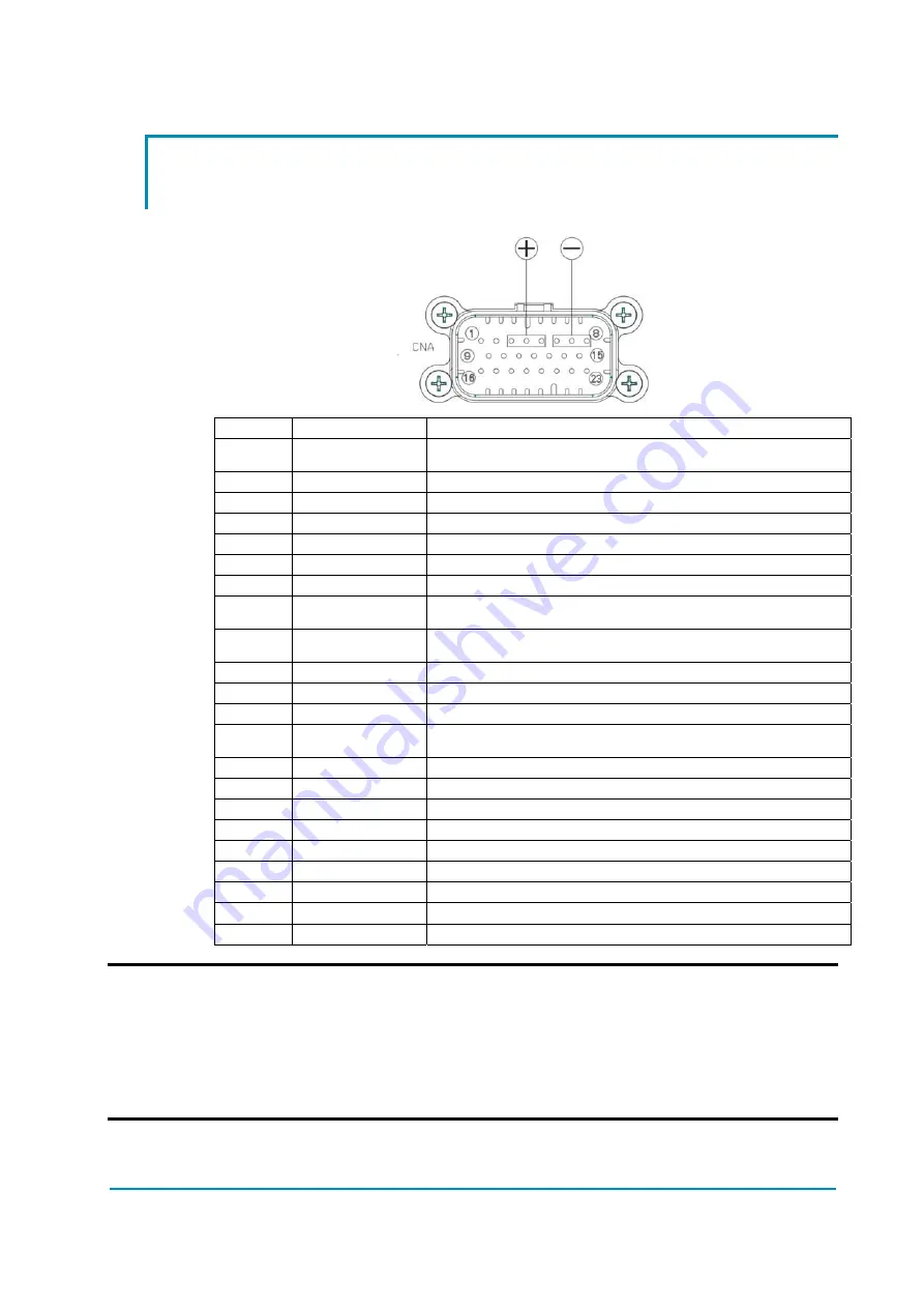
10.1 Connector assignment for a configuration with 1ENC, 2SWs
& 2CANs
23 poles AMPSEAL connector (CNA) assignment:
A1
FBPOT1
optional steered axle analog sensor output (0V...4.5V)
A2
VCC
13.5Vdc 200mA supply output (toggle switches or smart antennas
supply voltage)
A3
PBATT
PBATT power connection
A4
PBATT
PBATT power connection
A5
PBATT
PBATT power connection
A6
NBATT
NBATT power connection
A7
NBATT
NBATT power connection
A8
NBATT
NBATT power connection
A9
PCOILS
overcurrent and short-circuit protected positive breaker for coils.
A9 makes and takes Vbatt: 2Adc max @ Vbatt<=48V
A10
NCOIL
overcurrent and short-circuit protected negative breaker for a
proportional coil. A10 is a PWMout: 1.3Adc max @ Vbatt<=48V
A11
SW2
DIG_IN NPN type prox switch input
A12
SW1
DIG_IN NPN type prox switch input (straight ahead)
A13
GND
NBATT logic reference
A14
PCOIL2
short-circuit protected positive breaker for a proportional coil.
Cascaded with A9. A14 is a PWMout: 0.7Adc max @ Vbatt<=48V
A15
KEY IN
Key input (Logic Supply input)
A16
GND
1
ST
Stepper motor GND. NBATT logic reference
A17
QL
Stepper Motor Q Line (QL) or CPOC2 0-5Vdc
A18
VDD
5Vdc 50mA supply output (PPOT positive supply for FBPOT1)
A19
GND
2
ND
Stepper motor GND. NBATT logic reference
A20
DL
Stepper Motor D Line (DL) or CPOC1 0-5Vdc
A21
VDD
5Vdc 50mA supply output (PPOC positive supply for CPOC1-2)
A22
CANL1
CAN Bus 1, channel LOW (No 120
termination aboard)
A23
CANH1
CAN Bus 1, channel HIGH (No 120
termination aboard)
U
NOTE 1: For safety reason it is strongly recommended that TWO separated
GND connections (CNA#16 and CNA#19) are used from the stepper motor
to the epsacW.
NOTE 2: For closed loop applications (i.e. position control loop with a twin
pot analog command or automatic functions like automatic centering into
an aisle, release with two encoders in the motor is strongly recommended


