


H. ZANDER GmbH & Co. KG • Am Gut Wolf 15 • 52070 Aachen • Germany • Tel +49 241 9105010
Fax +49 241 91050138 • [email protected] • www.zander-aachen.de
30
Operating manual ZX09/20/21-Series
5.6
Digital Outputs
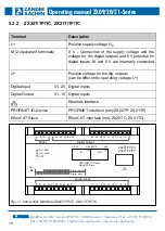
The ZX09 series controllers have 4 digital outputs and the ZX20/21 series controllers
have 16 digital outputs. These are accessible on the ZX20/21 series via the two upper
terminal blocks (see Fig. 20) and on the ZX09 series via the upper right terminal block
(see Fig. 19).
The outputs are not electrically isolated from the supply voltage, i.e. their 0 V reference
potential is identical to the 0 V potential of the supply voltage (terminal "M").
If the programmed logic of the user program switches one of the outputs, this is indi-
cated by four green LEDs to the right of the terminals (see Fig. 19). Here LED 1 corre-
sponds to output 1, LED 2 to output 2, etc. If one of the outputs is activated, it switches
through the voltage applied to U+, otherwise the output is open (ZX20/ZX21) or is
actively pulled to 0 V (ZX09 family).
All digital outputs are permanently short-circuit proof. This is only valid for real short
circuits, i.e. a low impedance connection with 0 V, not for overload.
Note:
In the "Structured Text", output variables for digital outputs may be
assigned to the above mentioned terminals by means of the keyword
"AT", namely by the designations "Out_01", "Out_02", ... , "Out_4" res.
"Out_16". Detailed information can be found in chapter 2.2.5.1 of the
programming manual, which is available as a PDF file in the software
package "EX_PRESS 5" (Art-no. 589092).
Note:
The acquisition of the TTL differential inputs or output to the TTL differen-
tial outputs is carried out in "EX_PRESS 5" (Art. No. 589092) via the
corresponding function blocks (see user manual for the program develop-
ment system EX_PRESS 5, Chapter 4.6 "Function blocks in user.lib")


