


H. ZANDER GmbH & Co. KG • Am Gut Wolf 15 • 52070 Aachen • Germany • Tel +49 241 9105010
Fax +49 241 91050138 • [email protected] • www.zander-aachen.de
13
Operating manual ZX09/20/21-Series
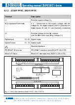
3.6.5 ZX20TP / ZX20TC / ZX21TP / ZX21TC
4.
Assembly
Please note:
The device must be installed in a switch cabinet or suitable housing with a minimum
degree of protection of IP54
Mount the controller on a 35 mm mounting rail according to EN 60715
Maintain a mounting distance of minimum 5 mm from the adjacent devices
Ensure that there is sufficient heat dissipation in the switch cabinet.
Keep the PLC away from devices or components, which carry high voltage or cause
strong electrical interference.
4.1
Assembly on the support rail
The black underside of the device is placed flat on the mounting rail (see Fig. 6). Then
press the unit firmly onto the mounting rail with your palms (see Fig. 7) until both or-
ange locking slides, which are located at the bottom, in the middle, on the long outer
sides and on the underside of the control unit, are engaged.
Fig. 5: Device diagram ZX20TP / ZX20TC / ZX21TP / ZX21TC
ZX20TP
ZX20TC
ZX21TP
ZX21TC


