


H. ZANDER GmbH & Co. KG • Am Gut Wolf 15 • 52070 Aachen • Germany • Tel +49 241 9105010
Fax +49 241 91050138 • [email protected] • www.zander-aachen.de
20
Operating manual ZX09/20/21-Series
5.5
Inputs
All device variants have digital inputs, and the ZX09A, ZX09B, ZX09C, ZX09D and
ZX09E variants also have analog inputs. These can be connected to the desired
sensor system via the lower terminal blocks "Digital Input" or "Analog Input".
If an input signal is applied to one of the inputs of a ZX20/21 series controller, this is
indicated by a green LED on the PLC (see Figs. 14A and 14B). The LEDs "01", "02",
"03", ... , "20" are continuously assigned to the digital inputs "01", "02", "03", ... , "20".
The ZX09 series do not have LEDs to indicate the input states.
108
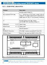
Fig. 13: Connection of the power supply of the ZX20T/TP/TC, ZX21T/TP/TC
U+
Power
L+
M
M
24 V
0 V
Note:
In the "Structured Text", input variables for digital inputs can be assigned
to the above-mentioned connection terminals via the keyword "AT" using
the designations "In_01", "In_02", ... , "In_10". Detailed information on this
can be found in the programming manual in Chapter 2.2.5.1
"VAR_INPUT / VAR_OUTPUT", which is included as a PDF file in the
software package "EX_PRESS 5" (Art. No. 589092) on the USB stick
included in the package.


