


H. ZANDER GmbH & Co. KG • Am Gut Wolf 15 • 52070 Aachen • Germany • Tel +49 241 9105010
Fax +49 241 91050138 • [email protected] • www.zander-aachen.de
31
Operating manual ZX09/20/21-Series
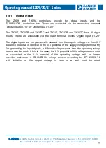
In the event of a short circuit or if there is no voltage at "U+", the "OC" LED to the left
of the terminals lights up on the ZX09 series controllers. When controlling inductive
loads, a protective circuit in the form of a free-wheeling diode or a varistor must be
provided.
It is possible to connect the supply voltage of the outputs without connecting the
operating voltage. In this case the outputs are not switched.
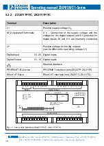
5.6.1 Connection of the digital outputs
The connection of the digital outputs of the ZX09 series is shown in fig. 19, the con-
nection of the ZX20/21 series in fig. 20. Different actuators (e.g. relays) can be con-
nected to the terminals of the outputs. Their 0 V potential is connected to the 0 V
potential of the voltage source for the digital outputs (terminal "M").
A voltage source must be connected to U+ and M so that a voltage is present when
the outputs are switched. This can be supplied via the operating voltage source or a
separate voltage source (10 V to 30 V, see chapter 12 "Technical Data"). If a separate
voltage source is used, an additional connection of the 0 V output of the voltage
source to the 0 V output of the operating voltage source is not necessary, since the
terminals "M" are connected to each other internally in the device.
Note:
Please observe the permissible voltage range for the digital outputs in
chapter 12 "Technical Data".
Warning:
The switching capacity information of the digital outputs specified in
chapter 12 "Technical data" must be observed.
In case of overload the output drivers can be destroyed.


