


67
YORK INTERNATIONAL
FORM 201.19-NM1 (204)
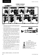
CAUTION:
No Controls (relays, etc.) should
be mount ed in the Smart Panel
en clo sure or con nect ed to pow er
sup plies in the control pan el.
Additionally, con trol wir ing not
con nect ed to the Smart Panel
should not be run through the
cabinet. This could re sult in
nui sance faults.
CAUTION:
Any inductive devices (re lays)
wired in series with the flow
switch for start/stop, into the
Alarm cir cuit ry, or pilot relays
for pump start ers wired through
mo tor contactor aux il ia ry con-
tacts must be sup pressed with
YORK P/N 031-00808-000
sup pres sor across the re lay/
contactor coil.
Any contacts con nect ed to
fl
ow
switch inputs or BAS in puts on
ter mi nals 13 - 19 or TB3, or any
oth er ter mi nals, must be sup-
pressed with a YORK P/N 031-
00808-000 sup pres sor across the
re lay/con tac tor coil.
CAUTION:
Control wiring con nect ed to the
con trol panel should nev er be run
in the same con duit with pow er
wir ing.
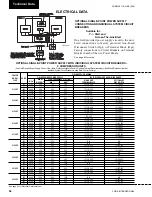
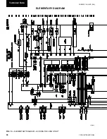
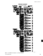
ELEMENTARY DIAGRAM
7
7
7
6
7
7
FANS
LD09235
UNIT
CONTROL
MIN
MAX DUAL
NON-FUSED
VOL
TAGE
POWER
CIRCUIT
ELEMENT
DISC.
SUPPL
Y
AMP
.
FUSE SIZE
SWITCH SIZE
ALL
MODELS
115-1-50/60
20A
20A
250V
30A
240V
W/O
TRANS.
MODELS
-17
200-1-60
15A
15A
250V
30A
240V
WITH
-28
230-1-60
15A
15A
250V
30A
240V
TRANS.
-46
400-1-60
8A
8A
600V
30A
480V
*
-58
575-1-60
8A
8A
600V
30A
600V
*
All pr
imar
y and secondar
y wir
ing betw
een tr
ansf
or
mer and control panel in
clud
ed.
CONTR
OL PO
WER SUPPL
Y
Summary of Contents for YCAS0130
Page 45: ...45 YORK INTERNATIONAL FORM 201 19 NM1 204 5 This page intentionally left blank...
Page 47: ...47 YORK INTERNATIONAL FORM 201 19 NM1 204 6 This page intentionally left blank...
Page 63: ...63 YORK INTERNATIONAL FORM 201 19 NM1 204 This page intentionally left blank 7...
Page 73: ...73 YORK INTERNATIONAL FORM 201 19 NM1 204 LD09239 FIG 22B CONTROL PANEL COMPONENT LOCATION 7...
Page 75: ...75 YORK INTERNATIONAL FORM 201 19 NM1 204 7 LEGEND LD09241...
Page 77: ...77 YORK INTERNATIONAL FORM 201 19 NM1 204 7 CONNECTION DIAGRAM SYSTEM WIRING LD09242...
Page 78: ...78 YORK INTERNATIONAL FORM 201 19 NM1 204 Technical Data COMPRESSOR TERMINAL BOX LD09243...
Page 79: ...79 YORK INTERNATIONAL FORM 201 19 NM1 204 7 LD09373 ELEMENTARY DIAGRAM CONTROL CIRCUIT...
Page 81: ...81 YORK INTERNATIONAL FORM 201 19 NM1 204 7 This page intentionally left blank...
Page 121: ...121 YORK INTERNATIONAL FORM 201 19 NM1 204 7 This page intentionally left blank...
Page 193: ...193 YORK INTERNATIONAL FORM 201 19 NM1 204 8 This page intentionally left blank...