


154
YORK INTERNATIONAL
FORM 201.19-NM1 (204)
Micro Panel Contents
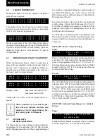
This message shows whether remote or local com mu -
ni ca tions was selected at the time of the fault.
This message displays the lead/lag selection pro-
grammed at the time of the fault.
This message indicates the leaving and return chilled
liquid temperature at the time of the fault.
This message indicates the mixed water temperature
at the time of the fault. A mixed water sensor may be
present when multi-unit sequencing is utilized. If no
mixed water temperature sensor is installed, the dis play
will not appear.
This message displays the programmed chilled liquid
setpoint and deviation (control range) programmed at
the time of the fault.
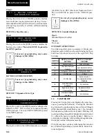
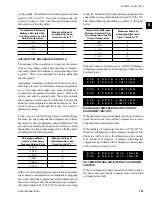
This message indicates the outdoor Ambient Air Tem-
per a ture at the time of the fault.
This message indicates which system was in the lead at
the time of the fault.
L O C A L / R E M O T E M O D E
L O C A L
L E A D / L A G C O N T R O L
A U T O M A T I C
L C H L T = 4 4 . 1 ° F
R C H L T = 5 2 . 9 ° F
M C H L T = 4 3 . 8 ° F
S E T P O I N T = 4 4 . 0 ° F
R A N G E = + / - 2 . 0 ° F
This message indicates the status of both the evap o ra tor
pump signal from the microprocessor and the evap o -
ra tor heater.
This message indicates that a remote device such as a
Remote Control Center, an ISN controller, or an oth er de-
vice is sending a PWM signal for tem per a ture or cur rent
reset is over rid ing control points programmed through
the keypad or default mi cro pro ces sor setpoints.
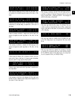
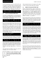
System Data:
Following the Common Data is a sequence of twen ty
information displays which are given twice,
fi
rst for
Sys tem 1, then for System 2. In each example, “#” is
used to indicate System number:
This message indicates whether the compressor on this
system was ON or OFF at the time of the fault.
This message shows the Run Time logged on the sys tem
since the last compressor start, in Days (D), Hours (H),
Minutes (M), and Seconds (S).
This message indicates the compressor motor current in
amps and as a percentage of Full Load Amps.
A M B I E N T A I R T E M P
7 7 . 6 ° F
L E A D S Y S T E M I S
S Y S T E M N U M B E R 1
E V A P P U M P I S O N
E V A P H E A T E R I S O F F
A C T I V E R E M O T E C T R L
N O N E
S Y S # C O M P R E S S O R
I S O N
S Y S # R U N T I M E
1 - 3 - 4 8 - 1 7 D - H - M - S
S Y S # M O T O R C U R R E N T
1 3 5 A M P S 7 8 % F L A
Summary of Contents for YCAS0130
Page 45: ...45 YORK INTERNATIONAL FORM 201 19 NM1 204 5 This page intentionally left blank...
Page 47: ...47 YORK INTERNATIONAL FORM 201 19 NM1 204 6 This page intentionally left blank...
Page 63: ...63 YORK INTERNATIONAL FORM 201 19 NM1 204 This page intentionally left blank 7...
Page 73: ...73 YORK INTERNATIONAL FORM 201 19 NM1 204 LD09239 FIG 22B CONTROL PANEL COMPONENT LOCATION 7...
Page 75: ...75 YORK INTERNATIONAL FORM 201 19 NM1 204 7 LEGEND LD09241...
Page 77: ...77 YORK INTERNATIONAL FORM 201 19 NM1 204 7 CONNECTION DIAGRAM SYSTEM WIRING LD09242...
Page 78: ...78 YORK INTERNATIONAL FORM 201 19 NM1 204 Technical Data COMPRESSOR TERMINAL BOX LD09243...
Page 79: ...79 YORK INTERNATIONAL FORM 201 19 NM1 204 7 LD09373 ELEMENTARY DIAGRAM CONTROL CIRCUIT...
Page 81: ...81 YORK INTERNATIONAL FORM 201 19 NM1 204 7 This page intentionally left blank...
Page 121: ...121 YORK INTERNATIONAL FORM 201 19 NM1 204 7 This page intentionally left blank...
Page 193: ...193 YORK INTERNATIONAL FORM 201 19 NM1 204 8 This page intentionally left blank...