


179
YORK INTERNATIONAL
FORM 201.19-NM1 (204)
8.9 SERVICE MODE: UNIT SETUP
The Service Mode allows programming unit set-up
values. These values are programmed before the
chiller leaves the factory and typically should never
be changed.
Catastrophic failure of chiller compo-
nents can occur if the set-up values are
improperly programmed. If for some
reason these values need to be checked
or changed, care should be exercised.
Whenever an EPROM is changed, the
programmed values should be record-
ed prior to removing the old EPROM.
These values should then be checked
and programmed into the micro when
the new EPROM is installed.
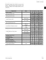
Setup values may be checked in the Service Mode by
pressing the PROGRAM, 5144, and ENTER keys.
Table 5 lists the value and the program range that will
be accepted.
SETUP MODE VALUE
PROGRAMMABLE RANGE
Refrigerant Type
R-22 or R-407C
R-407C Chiller Type
Optimized or Drop-in
Unit Type
YCAS or YCWS
**
Heat Recovery Unit
Enabled or Disabled
***
Sys 1 100% Full Load Amps
75 to 500 Amps
*
Sys 2 100% Full Load Amps
75 to 500 Amps
*
Sys 1 Motor Protector Input
1.0 to 5.0 volts
*
Sys 2 Motor Protector Input
1.0 to 5.0 volts
*
Oil Cooling On
167 to 203 ºF
180 ºF default
****
Oil Cooling Diff
9 to 18 ºF
9 ºF default
****
Discharge Cooling On
176.0 to 239.0 ºF
212.0 ºF default
Discharge Cooling Diff
7.2 to 27.0 ºF
18 ºF default
Data Logging Mode
OFF or ON
Data Logging Timer
6 to 60 seconds
Sys 1 Operating Hours
0 to 99,999
Sys 2 Operating Hours
0 to 99,999
Sys 1 Starts
0 to 99,999
Sys 2 Starts
0 to 99,999
Clear History Buffer
YES or NO
NOTE:
* See Table 6 or 7 for programming system 100% Full
Load Amps and System Motor Protector input volt-
age. Also assure that the correct number of wires
per phase pass through each C.T. The C.T. is built
internally into the 2ACE motor protector.
** The chiller must always be programmed for YCAS
*** Heat recovery must always be disabled.
**** Oil and discharge cooling is only utilized on spe-
cial low temp chiller.
TABLE 5 –
SERVICE MODE
PROGRAMMABLE
VALUES
Summary of Contents for YCAS0130
Page 45: ...45 YORK INTERNATIONAL FORM 201 19 NM1 204 5 This page intentionally left blank...
Page 47: ...47 YORK INTERNATIONAL FORM 201 19 NM1 204 6 This page intentionally left blank...
Page 63: ...63 YORK INTERNATIONAL FORM 201 19 NM1 204 This page intentionally left blank 7...
Page 73: ...73 YORK INTERNATIONAL FORM 201 19 NM1 204 LD09239 FIG 22B CONTROL PANEL COMPONENT LOCATION 7...
Page 75: ...75 YORK INTERNATIONAL FORM 201 19 NM1 204 7 LEGEND LD09241...
Page 77: ...77 YORK INTERNATIONAL FORM 201 19 NM1 204 7 CONNECTION DIAGRAM SYSTEM WIRING LD09242...
Page 78: ...78 YORK INTERNATIONAL FORM 201 19 NM1 204 Technical Data COMPRESSOR TERMINAL BOX LD09243...
Page 79: ...79 YORK INTERNATIONAL FORM 201 19 NM1 204 7 LD09373 ELEMENTARY DIAGRAM CONTROL CIRCUIT...
Page 81: ...81 YORK INTERNATIONAL FORM 201 19 NM1 204 7 This page intentionally left blank...
Page 121: ...121 YORK INTERNATIONAL FORM 201 19 NM1 204 7 This page intentionally left blank...
Page 193: ...193 YORK INTERNATIONAL FORM 201 19 NM1 204 8 This page intentionally left blank...