


167
YORK INTERNATIONAL
FORM 201.19-NM1 (204)
should have the cutout set at 395 PSIG (27 bar) for R22
and R407C models. The micro will, however, accept
val ues between 200 - 399 PSIG (14 - 28 bar).
To program the Discharge Pressure Cutout, key in the
desired value and press the Enter key to store the value
into memory and scroll to the next display.
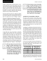
High Discharge Pressure Unload Point
The Discharge Pressure Unload point is used to avoid
a high pressure cutout shutdown by unloading a com-
pres sor, if its discharge pressure approaches the cutout
val ue. The chiller can then continue to run automatically
at reduced capacity until the cause of the excessive pres-
sure is attended to (e.g. dirty condenser coils) or ceas es
naturally (e.g. high ambient temperature).
For the
fi
rst 60 seconds of operation, discharge pres-
sure limiting is disabled. After this time, if discharge
pressure exceeds the programmed limit, un loading of
the affected compressor will occur until the discharge
pres sure drops below the programmed limit. The mes-
sage will be removed and reloading will take place
when dis charge pressure has dropped to 90% of the
programmed unload point..
Typically the unload point should be set 20 - 25 PSIG
(1.4 - 1.7 bar) below the below the discharge pressure
cutout setting. The micro will accept a range of pro gram -
ma ble values between 200 - 399 PSIG (14 - 28 bar).
To program the Discharge Pressure Unload, key in the
required setting and press the Enter key to store the value
into memory and scroll to the next display.
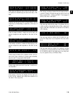
Low Suction Pressure Cutout
The Low Suction Pressure Cutout protects the evap o -
ra tor from damage due to ice build up caused by op-
er a tion at low refrigerant suction pressure.
After the compressor starts, and the pump down cycle is
completed (pump down to cutout or 30 seconds, which-
ev er comes
fi
rst.), suction pressure is monitored as long
as the compressor runs. For the
fi
rst 270 sec onds of run-
ning, suction pressure can be lower than the pro grammed
cutout, but must be greater than:
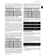
This cutout value increases with time, until after 270 sec-
onds, it equals the programmed cutout value. If suc tion
pressure falls below the calculated cutout value before
270 seconds, the system will be shut down.
After 270 seconds, a transient timer prevents short term
fl
uctuations in suction pressure from caus ing shutdown
as follows: If suction pressure drops be low the cutout
point, a 90 second transient timer starts. Dur ing the 90
second time period, the suction pressure must be greater
than:
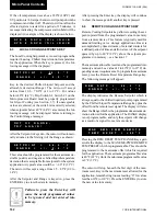
This cutout value increases with time, until after 90
sec onds, it equals the programmed cutout value. If the
suc tion pressure rises to more than 5 PSI (0.3 bar) above
the programmed cutout value during the 90 second time
period, the timer will be reset. If the suction pressure
does not rise to more than 5 PSI (0.3 bar) above the
cutout, the timer will remain at zero and if the pressure
then falls below the cutout again, the system will shut
down on a low pressure fault.
If the Dip Switch on the microprocessor board is set
for “Water Cooling” (see Section 3.7), the cutout is
pro gram ma ble between 44 - 70 PSIG (3-5 bar) for both
R22 and R-407c models. In this mode, settings of 44
PSIG (3 bar) for R22 and R-407C are recommended. If
the Switch is set for “Brine Cooling” (glycol) the cut out
is programmable between 5 - 70 PSIG (0.3 bar) for R22
and R-407c models. In this mode, the cutout should be
S U C T I O N P R E S S U R E
C U T O U T = 4 4 . 0 P S I G
D I S C H A R G E P R E S S U R E
U N L O A D = 3 6 0 . 0 P S I G
Programmed
100 - transient time remaining
Cutout
100
Example: If programmed Cutout = 44 PSIG (3 bar)
and the timer has run 30 seconds:
New Cutout = 44 PSIG X 100-60 = 17.6 PSIG (1.2 bar)
100
X
Programmed X Run Time/3 + 10
Cutout 100
Example: If programmed Cutout = 44 PSIG (3 bar)
and Run Time = 60 seconds
60/3 + 10
100
New Cutout = 44 X
= 13.2 PSIG (0.9 bar)
8
Summary of Contents for YCAS0130
Page 45: ...45 YORK INTERNATIONAL FORM 201 19 NM1 204 5 This page intentionally left blank...
Page 47: ...47 YORK INTERNATIONAL FORM 201 19 NM1 204 6 This page intentionally left blank...
Page 63: ...63 YORK INTERNATIONAL FORM 201 19 NM1 204 This page intentionally left blank 7...
Page 73: ...73 YORK INTERNATIONAL FORM 201 19 NM1 204 LD09239 FIG 22B CONTROL PANEL COMPONENT LOCATION 7...
Page 75: ...75 YORK INTERNATIONAL FORM 201 19 NM1 204 7 LEGEND LD09241...
Page 77: ...77 YORK INTERNATIONAL FORM 201 19 NM1 204 7 CONNECTION DIAGRAM SYSTEM WIRING LD09242...
Page 78: ...78 YORK INTERNATIONAL FORM 201 19 NM1 204 Technical Data COMPRESSOR TERMINAL BOX LD09243...
Page 79: ...79 YORK INTERNATIONAL FORM 201 19 NM1 204 7 LD09373 ELEMENTARY DIAGRAM CONTROL CIRCUIT...
Page 81: ...81 YORK INTERNATIONAL FORM 201 19 NM1 204 7 This page intentionally left blank...
Page 121: ...121 YORK INTERNATIONAL FORM 201 19 NM1 204 7 This page intentionally left blank...
Page 193: ...193 YORK INTERNATIONAL FORM 201 19 NM1 204 8 This page intentionally left blank...