


140
YORK INTERNATIONAL
FORM 201.19-NM1 (204)
High Discharge Pressure Cutout:
The Discharge Pressure Safety prevents system pres sure
from exceeding safe working limits. This safety is a
backup for the mechanical High Pres sure Cutout in each
system. The Discharge Pressure Safety is pro gram ma ble
for a range of values below the system up per limit (see
Section 8.2 / Page 166, High Discharge Pres sure Cutout
for more details).
High Discharge Temperature Cutout:
This safety protects the compressor rotors from dam age
due to overheating, expansion, and breakdown of the oil
fi
lm seal between the rotors. It also protects against ex-
cessive oil temperature in the discharge oil separator.
For the
fi
rst 4 seconds of operation discharge tem-
per a ture is ignored. After 4 seconds of operation the
com pres sor will shut down if the discharge temperature
ex ceeds 260°F (127°C).
High Oil Differential Pressure Cutout:
The High Oil Pressure Differential Safety protects the
compressors against loss of proper lubrication due to
oil line blockage. The “differential oil pressure” for this
safety is computed by measuring discharge pressure and
subtracting oil pressure re turn ing to the compressor
(Discharge - Oil = Oil PSID). Under normal operation,
the oil pressure differential dis play will be less than 25
PSID (1.7 bar), typical 2 - 10 PSID (0.1 to 0.7 bar). If
oil pres sure at the com pres sor drops due to
fi
l ter block-
age, the dif fer en tial pres sure on the dis play will in crease
and when the max i mum limit is reached, the com pres sor
will be shut down.
This safety is activated after 3 minutes of operation. Oil
pressure must be less than 65 PSID (4.4 bar) for R22
models as long as the compressor continues to run.
Flow Switch Open:
Closure of the
fl
ow switch is monitored to check that
fl
ow is present in the evaporator when a com pres sor
is running. Any external cy cling de vic es
fi
tted by the
customer are connected in series with the
fl
ow switch.
YCAS 2 System chillers require a single
fl
ow switch
wired to the control panel. If the
fl
ow switch opens, all
sys tems will shut down and a NO RUN PERM (Per-
mis sive) mes sage will be dis played. Clos ing of the
fl
ow
switch, when
fl
ow is present, will cause the mes sage to
dis ap pear and auto-restart to oc cur.
Never bypass a
fl
ow switch. This will
cause dam age to the chiller and void
any war ran ties.
2.6
SYSTEM FAULT (SAFETY) STATUS
MESSAGES
A System Fault will shut the affected sys tem down
whenever a preset safety thresh old is ex ceed ed for 3
seconds. Automatic restart will occur af ter the
fi
rst 2
shut downs when the anti-re cy cle timer times out and
tem per a ture de mand exists. After any com bi na tion of 3
Manual Reset Safeties in a 90 minute time period, the
affected system will shut down and lock out on the last
fault. When one or more sys tems are shut down on one
of these safeties, a mes sage will appear on the Status
display in form ing the op er a tor of the prob lem.
The High Motor Current Safety is a
unique safe ty which will lock out a
sys tem after only a single fault.
To reset a locked out system, turn the Sys tem Switch
for the affected system to the OFF po si tion, then back
to the ON po si tion (see Sec tion 1.11, Page 130, Fig. 46
for switch locations).
Before returning a locked out sys tem
to ser vice, a thorough investigation of
the cause of the fault should be made.
Fail ure to repair the cause of the fault
while manually al low ing re pet i tive
re starts may cause fur ther ex pen sive
damage to the system.
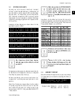
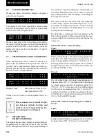
S Y S # H I G H D S C H P R E S
S Y S # H I G H D S C H P R E S
S Y S # H I G H D S C H T E M P
S Y S # H I G H D S C H T E M P
S Y S # H I G H O I L D I F F
S Y S # H I G H O I L D I F F
Micro Panel Contents
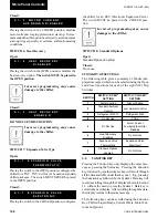
S Y S # N O R U N P E R M
S Y S # N O R U N P E R M
Summary of Contents for YCAS0130
Page 45: ...45 YORK INTERNATIONAL FORM 201 19 NM1 204 5 This page intentionally left blank...
Page 47: ...47 YORK INTERNATIONAL FORM 201 19 NM1 204 6 This page intentionally left blank...
Page 63: ...63 YORK INTERNATIONAL FORM 201 19 NM1 204 This page intentionally left blank 7...
Page 73: ...73 YORK INTERNATIONAL FORM 201 19 NM1 204 LD09239 FIG 22B CONTROL PANEL COMPONENT LOCATION 7...
Page 75: ...75 YORK INTERNATIONAL FORM 201 19 NM1 204 7 LEGEND LD09241...
Page 77: ...77 YORK INTERNATIONAL FORM 201 19 NM1 204 7 CONNECTION DIAGRAM SYSTEM WIRING LD09242...
Page 78: ...78 YORK INTERNATIONAL FORM 201 19 NM1 204 Technical Data COMPRESSOR TERMINAL BOX LD09243...
Page 79: ...79 YORK INTERNATIONAL FORM 201 19 NM1 204 7 LD09373 ELEMENTARY DIAGRAM CONTROL CIRCUIT...
Page 81: ...81 YORK INTERNATIONAL FORM 201 19 NM1 204 7 This page intentionally left blank...
Page 121: ...121 YORK INTERNATIONAL FORM 201 19 NM1 204 7 This page intentionally left blank...
Page 193: ...193 YORK INTERNATIONAL FORM 201 19 NM1 204 8 This page intentionally left blank...