


23
YORK INTERNATIONAL
FORM 201.19-NM1 (204)
Single-Point Power Connection with Combined
Cir cuit Protection
A single-point supply circuit with field provided
pro tec tion is connected to a factory provided circuit
break er with lockable external handle located in the
options com part ment. Factory wiring is provided from
the cir cuit breaker to factory supplied terminal blocks
in the power compartments.
Single-Point Power Connection without Circuit
Protection
A single-point supply circuit with
fi
eld provided pro-
tec tion is connected to a factory provided terminal block
or non-fused disconnect switch located in the options
com part ment. Factory wiring is provided from the ter-
mi nal block or disconnect switch to factory supplied
terminal blocks in the power compartments.
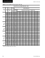
Control Circuit Terminal Block
A 120V, 20A control circuit power terminal strip lo cat ed
in the control panel to accept a
fi
eld provided control
power supply, rather than the standard factory mounted
control circuit transformer. The supply with appropriate
branch circuit protection in accordance with applicable
Local codes, provides the unit control cir cuit power sup-
ply via the panel mounted Emergency Stop Switch.
Building Automation System (BAS) Interface
Provides a means to reset the leaving chilled liquid tem-
per a ture or percent full load amps (current limiting) from
the BAS (Factory-mounted):
Printed circuit board to accept 4 to 20mA, 0 to 10VDC,
or dry contact closure input from the BAS.
A YORK ISN Building Automation System can pro-
vide a Pulse Width Modulated (PWM) signal direct to
the standard control panel via the standard on-board
RS485 port.
Condenser Coil Protection
The standard condenser coils have Aluminum
fi
ns, cop-
per tubes, and galvanized steel supports for generally
adequate corrosion resistance. However, these ma te ri als
are not adequate for all environments.
Entry
–
Used to con
fi
rm Set Point changes, cancel
in puts, advance day, and change AM/PM.
Setpoints
–
For setting chilled liquid temperature,
chilled liquid range, remote reset temperature range.
Clock
–
Used to set time, daily or holiday start/stop
schedule and manual override for servicing.
–
Used to display or print operating data or sys-
tem fault shutdown history for last six faults. Printouts
through an RS-232 port via a separate print er.
Program
For setting low leaving liquid temperature cutout, 300
to 600 second anti-recycle timer, average motor cur rent
unload point, liquid temperature setpoint reset sig nal
from YORK ISN or building automation system.
Additional functions (password protected) for pro-
gram ming by a quali
fi
ed service technician:
Cutouts for low and high ambient, low suction pres-
sure and high discharge pressure, refrigerant type, high
dis charge pressure unload setpoint.
ACCESSORIES AND OPTIONS
Multiple Point Power Connection (Standard)
Standard
fi
eld power wiring connection on all models
is Multiple Point Power Connection. Field provided
pow er supply circuits, with appropriate branch circuit
pro tec tion, are connected to factory provided terminal
blocks, non-fused disconnect switches or circuit break ers
with lockable external handles located in the two power
com part ments.
Single-Point Power Connection with Individual
Circuit Protection
A single-point supply circuit with
fi
eld provided pro-
tec tion is connected to a factory provided terminal block
or non-fused disconnect switch located in the options
com part ment. Factory wiring is provided from the ter-
mi nal block or disconnect switch to factory supplied
internal branch circuit breakers with lockable external
handles in the power compartments.
2
Summary of Contents for YCAS0130
Page 45: ...45 YORK INTERNATIONAL FORM 201 19 NM1 204 5 This page intentionally left blank...
Page 47: ...47 YORK INTERNATIONAL FORM 201 19 NM1 204 6 This page intentionally left blank...
Page 63: ...63 YORK INTERNATIONAL FORM 201 19 NM1 204 This page intentionally left blank 7...
Page 73: ...73 YORK INTERNATIONAL FORM 201 19 NM1 204 LD09239 FIG 22B CONTROL PANEL COMPONENT LOCATION 7...
Page 75: ...75 YORK INTERNATIONAL FORM 201 19 NM1 204 7 LEGEND LD09241...
Page 77: ...77 YORK INTERNATIONAL FORM 201 19 NM1 204 7 CONNECTION DIAGRAM SYSTEM WIRING LD09242...
Page 78: ...78 YORK INTERNATIONAL FORM 201 19 NM1 204 Technical Data COMPRESSOR TERMINAL BOX LD09243...
Page 79: ...79 YORK INTERNATIONAL FORM 201 19 NM1 204 7 LD09373 ELEMENTARY DIAGRAM CONTROL CIRCUIT...
Page 81: ...81 YORK INTERNATIONAL FORM 201 19 NM1 204 7 This page intentionally left blank...
Page 121: ...121 YORK INTERNATIONAL FORM 201 19 NM1 204 7 This page intentionally left blank...
Page 193: ...193 YORK INTERNATIONAL FORM 201 19 NM1 204 8 This page intentionally left blank...