


155
YORK INTERNATIONAL
FORM 201.19-NM1 (204)
8
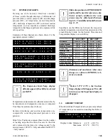
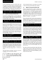
This message indicates the system oil pressure, suc-
tion pressure, and discharge pressure at the time of the
fault.
This message shows the system oil temperature, suction
temperature, and discharge temperature at the time of
the fault.
These messages indicate compressor suction gas sat-
u ra tion temperature and superheat at the time of the
fault.
This message indicates compressor discharge gas sat-
u ra tion temperature and superheat at the time of the
fault.
This message indicates the compressor slide valve po-
si tion at the time of the fault. 0 steps equals minimum
capacity and 75 steps equals fully loaded.
This message indicates the EEV preheat % and the suc-
tion superheat.
This message, which is only displayed if the unit is in
R-407C mode, indicates the refrigerant temperature at
the inlet of the evaporator.
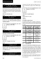
S Y S # O I L = 1 5 4 . 8 ° F
S T = 3 9 . 0 D T = 1 2 3 . 7 ° F
S Y S # O I L = 1 7 5 P S I G
S P = 6 2 D P = 2 7 1 P S I G
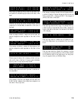
S # S A T S U C T = 3 4 . 7 ° F
S U C T S H E A T = 1 0 . 5 ° F
S # S A T D S C H = 1 2 9 ° F
D S C H S H E A T = 6 2 . 8 ° F
S Y S # S V S T E P = 4 0
S Y S # C O O L E R I N L E T
R E F R I G T E M P = 2 8 . 2 ° F
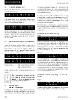
S Y S # L L S V I S O N
E C O N T X V S O L I S O F F
S Y S # F A N S T A G E 3
C O M P H E A T E R I S O F F
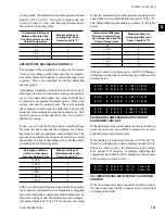
This message indicates the EEV PILOT So le noid Valve
and the economizer Thermal Expansion Valve So le noid
Valve position: ON = Energized / OFF = De-En er gized
(OFF) at the time of the fault.
This message indicates the stage of condenser fan op-
er a tion on the system and the status of the com pres sor
heat er at the time of the fault. See Section 8.4 for de tails
of fan staging.
This message indicate whether the WYE-DELTA out-
put to the compressor was energized at the time of the
fault
This message indicates whether the discharge cooling
solenoid was energized at the time of the fault and if the
WYE-DELTA output to the compressor was energized.
(Low Temperature Glycol Chillers Only)
S Y S X E E V = 3 7 . 4 %
S U C T S H E A T = 1 0 . 2 º F
S Y S # W Y E - D E L T A O N
S Y S X D S C H C L S V OFF
S Y S X W Y E - D E L T A OFF
Summary of Contents for YCAS0130
Page 45: ...45 YORK INTERNATIONAL FORM 201 19 NM1 204 5 This page intentionally left blank...
Page 47: ...47 YORK INTERNATIONAL FORM 201 19 NM1 204 6 This page intentionally left blank...
Page 63: ...63 YORK INTERNATIONAL FORM 201 19 NM1 204 This page intentionally left blank 7...
Page 73: ...73 YORK INTERNATIONAL FORM 201 19 NM1 204 LD09239 FIG 22B CONTROL PANEL COMPONENT LOCATION 7...
Page 75: ...75 YORK INTERNATIONAL FORM 201 19 NM1 204 7 LEGEND LD09241...
Page 77: ...77 YORK INTERNATIONAL FORM 201 19 NM1 204 7 CONNECTION DIAGRAM SYSTEM WIRING LD09242...
Page 78: ...78 YORK INTERNATIONAL FORM 201 19 NM1 204 Technical Data COMPRESSOR TERMINAL BOX LD09243...
Page 79: ...79 YORK INTERNATIONAL FORM 201 19 NM1 204 7 LD09373 ELEMENTARY DIAGRAM CONTROL CIRCUIT...
Page 81: ...81 YORK INTERNATIONAL FORM 201 19 NM1 204 7 This page intentionally left blank...
Page 121: ...121 YORK INTERNATIONAL FORM 201 19 NM1 204 7 This page intentionally left blank...
Page 193: ...193 YORK INTERNATIONAL FORM 201 19 NM1 204 8 This page intentionally left blank...