background image

《目次》 《索引》

TI 71M01D03-03

1st Edition : 2007.03.12-00

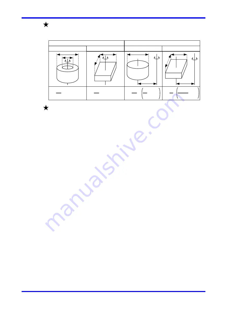
Moment inertia of load mounted to rotation motor (DYNASERV) [kg・m

2

]

Shapes and formulas are as below.

Load inertia

Column

Rectangle

Rectangle

Column

Axis go through center of gravity

Axis does not go through center of gravity

a

b

a

b

r

a

r

a

b

J=

1
8

M(a

2

+b

2

)

J=

1

12

M(a

2

+b

2

)

J=

1
4

M   a

2

+4r

2

1
2

J=

1
4

a

2

+b

2

M      +4r

2

3

Reboot
Power recycle, or restart drive by software reset command

付-2

Summary of Contents for DrvGIII

Page 1: ...ARSERV system This manual is the auxiliary instruction in regard to these Technical Information hereinafter called as TI and product handling Contents of this manual may be revised without notice due...

Page 2: ...Auto tuning can not be completed 1 5 1 8 Direct entry of inertia or mass 1 5 STEP2 Servo stiffness setup 2 1 2 1 Improve servo stiffness as much as possible 2 1 2 2 Filter set up 2 2 2 3 Set notch fil...

Page 3: ...sitioning command 6 4 6 2 2 Create the table data 6 4 6 2 3 Use copy and paste function 6 5 6 2 4 Test operation of table data using software 6 6 6 2 5 Execute table data operation by PLC 6 6 6 2 6 Ph...

Page 4: ...e factory default settings Refer to Q3 of Q A in the Appendix For further details refer to the Technical Information Device configuration when tuning Symbols in this maual i Warning Warning to avoid u...

Page 5: ...stiffness adjustment STEP 6 1 Homing 2 1 Filter setting STEP 3 Calculation of acc and dec time STEP 0 Setup Positioning setup ii STEP 5 1 Homing STEP 4 Scaling STEP 5 2 Pulse command operation STEP 6...

Page 6: ...DEVICE MANAGER Check COM port number from Port COM and LPT ex COM1 1 Setup Flow 1 1 2 2 3 3 4 5 4 5 6 6 See also 8 3 2 Communication Settings in the TI 0 1 Note Above windows are just sample It may d...

Page 7: ...e the drive is connected with the motor Connection is completed Now you can send variety of commands to the drive Continue the operation according to this manual 7 7 8 9 8 9 If the drive stings are no...

Page 8: ...motor may unexpectedly move Operation Flow Click Terminal button Terminal Window Command entry edit box Transmission receiption edit box See also 8 4 2 Terminal in the TI Terminal window is displayed...

Page 9: ...8 4 2 1 9 3 Epexegesis Entry method Registration is completed However parameter 110 to 122 require recycling main power or driver reset 96 for the registration Ex1 How to resister change the value of...

Page 10: ...call your nearest contact with the error number 0 5 If error LED is righted Operation Flow 0 6 Error monitoring Click START Click Error mon Error is displayed Click STOP Cause and measure are displaye...

Page 11: ...traint of your instrument 1 1 Execute auto tuning Operation Flow Click Drive Click Yes Click Servo on Click Drive Click Regist Click Auto tuning operation If an error is called or motor oscillates Ref...

Page 12: ...ut 20 from calculated values however it s been no problem at all If the value is marked contrast to the calculated value execute the auto tuning again or proceed to 1 7 Auto tuning can not be complete...

Page 13: ...ick Filter setup Hereinafter this window shall be referred if it is described as Filter setup window Filter setup window 10 11 10 12 12 002 for velocity control bandwidth 008 for position control band...

Page 14: ...ording to the following instruction Motor oscillates widely when executing auto tuning Please be careful Refer 0 4 Change parameters via terminal window also Example of terminal window 51 51 Check val...

Page 15: ...please enter load inertia mass value directly according to the following steps The unit is 1 1000 kgm 2 or kg 1 8 Direct entry of inertia mass Enter calculated value of load inertia mass then press re...

Page 16: ...much as possible Operation Flow Shift cursor of Servo stiffness setup to the right until a esonance appears Servo setting window See also 7 1 How to Tune the Servo in the TI 1 1 Seek the max value of...

Page 17: ...f resonance is not eliminated Check notch filter 2 2 4 Set the first lad compensation filter Check First lag compensation filter Check 40 160 Check 30 120 Check 20 80 Caution First lag compensation fi...

Page 18: ...e result of this computation may not be optimized Use the result as the reference Also the above acc dec time may differ depending on the PLC Set appropriate value upon checking the definition of PLC...

Page 19: ...and pulses Rotate 90 degrees Command pulse 90000 Rotate 206 32 degrees Command pulse 206320 For index command If total number of indexing points can not be divided by 360 it helps to simplify computat...

Page 20: ...nd by pulse trains Command by table data Go to STEP 6 2 Moveing command by table data Set the scaling data fixed in the previous page Proceed the setup with referring to 0 4 Change parameters via term...

Page 21: ...ive Models UD1A UD1B UR1A UR1B UR1E UR5B UR5E Z pulse generated by Hardware Software Z pulse ON duty Approx 10 1 excl UD1B 004 UD1B 006 UD1C Software UR5C Approx 50 UD1B 004 UD1B 006 1 Z pluses 1 rev...

Page 22: ...g across inaccurate edge Detection accuracy of home sensor output If the home sensor is turned ON OFF near the accurate edge the home position may be shifted by an amount equivalent to 1 pulse of the...

Page 23: ...rive CPU ready Servo ready COIN signal Pos command pulse1 Pos command pulse1 Pos command pulse2 Pos command pulse1 Monitor pulse1 Monitor pulse1 Monitor pulse2 Monitor pulse2 Z pulse Z pulse Pin Defin...

Page 24: ...type Command pulse type is the kind of pulse command issued by PLC Please choose it from the following 3 options PLS SIGN input UP DOWN CW CCW input A B input Refer to the following table for the spe...

Page 25: ...er 1 4 Select Command pulse type 3 4 5 5 Select Monitor pulse type 6 6 Click Regist 2 Parameter setup window is displayed Selected pulse types are registered Now setting and Now rebooted windows are p...

Page 26: ...tion error is output Refer to 5 2 Main Power Supply Control Power Supply Terminal TB1 for details Warning Ex Sensor EE SX670 made by Omron Refer 5 5 Sensor Terminal TB4 for sensor input specifications...

Page 27: ...Table data 2 5 5 Select Homing Complete Table setup window Hereinafter this window shall be referred if it is described as Table setup window 6 6 Select Enable for Coin waiting 7 7 Click Regist Table...

Page 28: ...ng operation again until the measurement result is inside the target 5 6 5 Click Servo off Click Error reset 6 Shift sensor dog around 0 5 deg On motor 7 7 Click Servo on 8 Drive window is displayed S...

Page 29: ...ABS are available to choose INC Commanding relative moving distance ABS Commanding absolute distance from home position Here INC positioning command is set as an example Select INC positioning from Co...

Page 30: ...11 Refer to ex2 Table data is registered and the creation of moving profile is completed Enter axis command pulse for 1 s Refer to ex1 12 14 15 16 Select Type2 multi turn for Optional direction for ro...

Page 31: ..._ERR_RESET 01 02 19 20 21 22 23 24 25 OUT_POS OUT_COIN OUT_DRDY OUT_SRDY 8 3 4 13 13 14 14 15 16 15 16 Signal Pin Definition Remark CN4 Interface power Interface power Error reset Drive execution comm...

Page 32: ...ion PLC Positioning signal Drv G T V Executed table number ON ON Motor Settling time Positioning signal becomes ON state after coin signal turns ON if Coin waiting is set Valid when creating table dat...

Page 33: ...g time Operation Flow 1 2 1 2 3 4 Click Oscilloscope Click EASY SETUP Select 06 Check of current command Click OK Signals necessary to be measured are automatically selected 4 5 5 Click START While di...

Page 34: ...forms become easy to look 7 3 Measure 8 9 10 11 12 6 7 8 9 Click CURSOR Check ON 10 Select dT or dV 11 12 Select channel to measure Select cursor to move Indicated only if dT is selected Represent Y...

Page 35: ...se deviation well following How to improve It may be caused by unbalance between velocity control bandwidth and position control bandwidth Decline position control bandwidth at 008 Reference What is g...

Page 36: ...tion Flow 7 6 Download parameters 3 4 5 6 7 3 4 5 6 7 Click Backup Click Upload Uploading is displayed then parameters are displayed Click Save as Click Open Click Download Parameters are stored in th...

Page 37: ...iable load more than 1 5 times may lead this vibration vibration frq a few Hz moving angle a few to a few dozens deg Low frequency vibration Wind up Phase shift osscilation Resonance High frequency vi...

Page 38: ...hapes and formulas are as below Load inertia Column Rectangle Rectangle Column Axis go through center of gravity Axis does not go through center of gravity a b a b r a r a b J 1 8 M a2 b2 J 1 12 M a2...

Page 39: ...em setup register 1 is displayed Position control I P control Velocity control Proportional Control mode Position mode Refer to Select appropriate control mode and method Regist button becomes valid o...

Page 40: ...03 03 1st Edition 2007 03 12 00 YOKOGAWA ELECTRIC CORPORATION Advanced Stage Division DDM Center YOKOGAWA ELECTRIC CORPORATION 2 9 32 Naka cho Musashino shi Tokyo 180 8750 JAPAN URL http www yokogawa...

Reviews: