


30
3-3-2 Setting the Wavelength
■
Selecting Typical Values (Specified Typical Wavelength)
Step
Key
Display
Description
1
SETUP
is displayed. The
light receiving mode indicator
blinks.
Changes to light
receiving mode
settings.
2
SETUP
The wavelength setting blinks
(ex. “850” blinks), and the light
receiving mode stops blinking.
Changes to wavelength
settings.
3 [UP]
or
[DOWN]
850nm => 1300nm =>
1310nm => 1490nm
=>1550nm => 1625nm =>
1650nm => previous value
=>USR => 850nm
Press the key
repeatedly to scroll
through the options
([DOWN] scrolls in
reverse). Select the
desired wavelength. If
you select USR, see [2]
below.
4
ENTER
The mode display stops
blinking.
ON or OFF blinks.
Selects the
measurement
wavelength. To enter
averaging settings, see
step 4 in section 3-3-3.
5 ENTER
changes
to
the
measured value display.
Exits measurement
wavelength settings.
(Note)
Previous value
refers to the previously set detail wavelength settings.
This is different from the factory default setting.
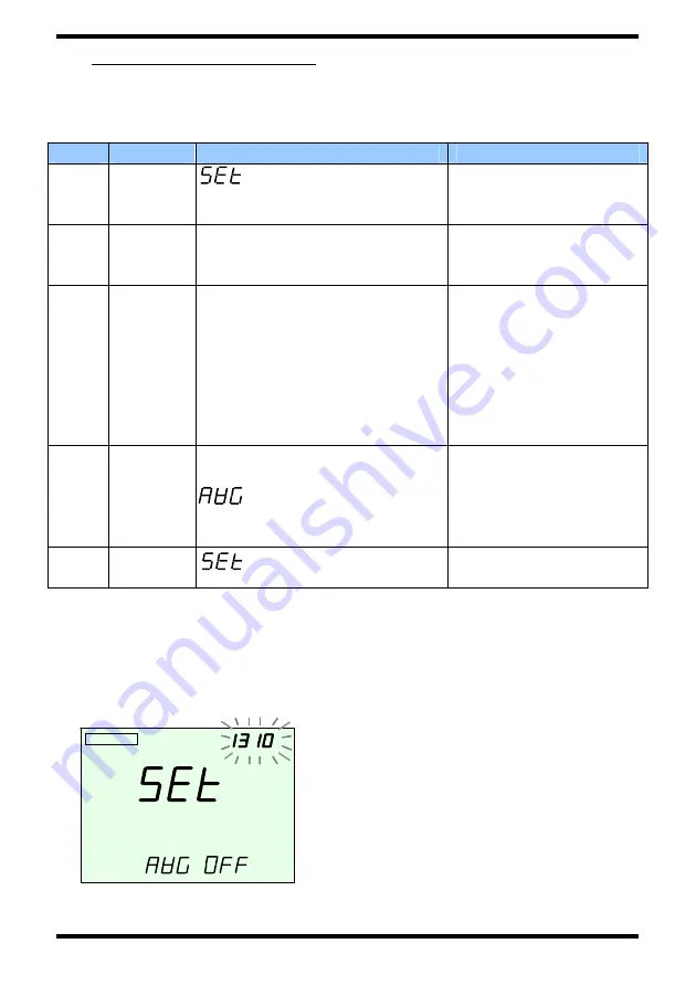
<Display Example> Wavelength Setting Selection Screen (Step 2)
Since the sensor element has
wavelength sensitivity characteristics,
the instrument stores a correction
value corresponding to the
wavelength.
For accurate measurements, you
must set the instrument’s wavelength
setting to match the wavelength of the
optical power to be measured.
PWR SAVE
▲
▼
nm
CW
PWR SAVE
PWR SAVE
▲
▼
nm
nm
CW