


3.2 Settings for Triggers at Preset Positions
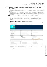
3.2.2 Setting Triggers at Preset Positions
3-8
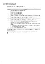
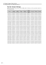
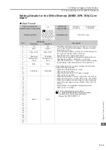
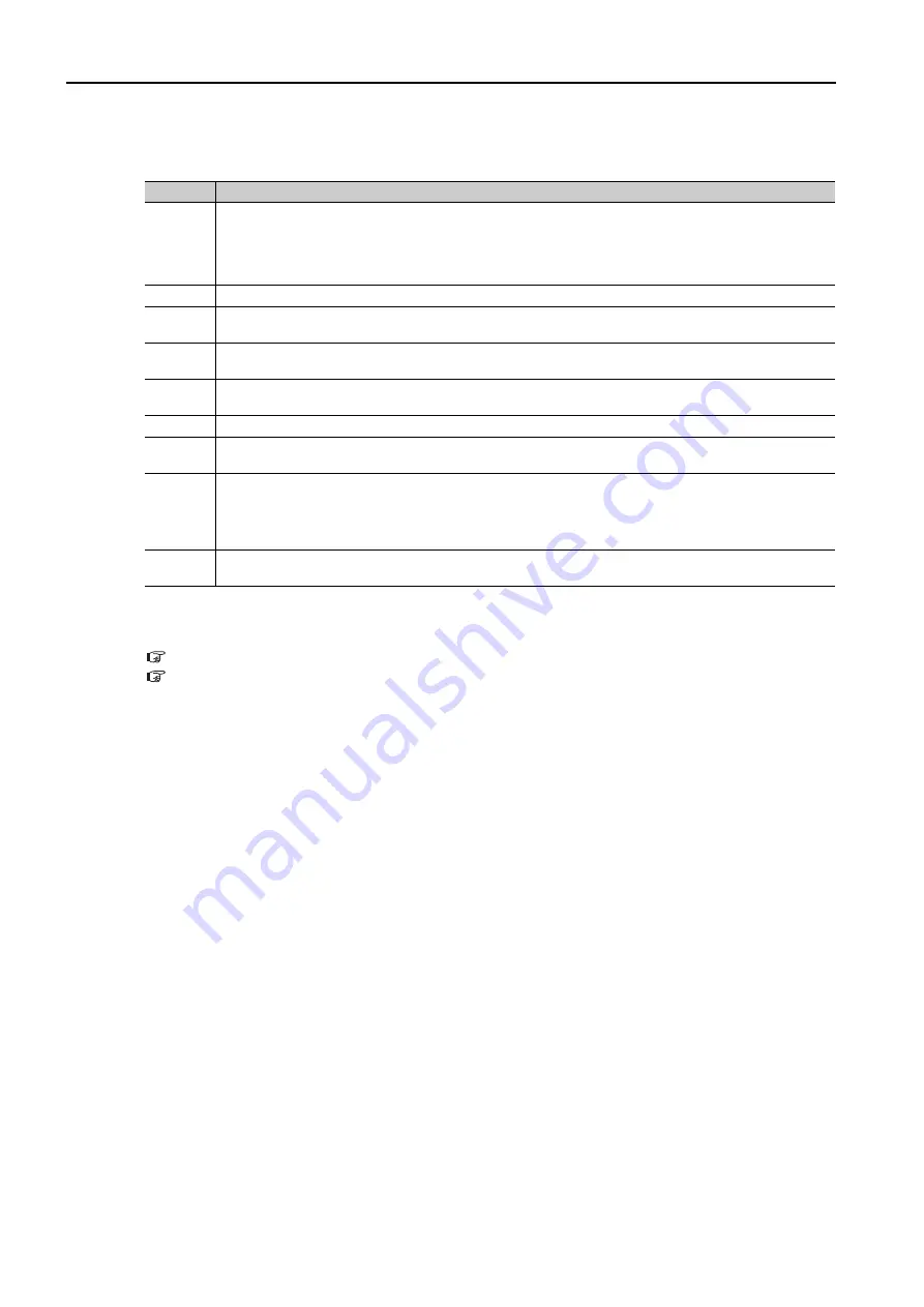
Normal Output Setting Method
This section describes the procedure to execute normal outputs with the MEM_WR command.
You can make the settings for steps 2, 3, 5, and 6 from the S or by executing the
MEM_WR command.
Refer to the following sections for details on the settings and then make the settings.
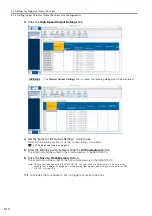
3.2.3 Setting Trigger Outputs at Preset Positions with the S
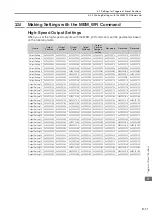
3.2.4 Making Settings with the MEM_WR Command
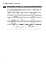
Step
Operation
1
Set the following output signal selections 1 to 4.
•
Pn50E (Output Signal Selections 1)
•
Pn50F (Output Signal Selections 2)
•
Pn510 (Output Signal Selections 3)
•
Pn514 (Output Signal Selections 4)
2
Set the output position in reference units.
3
Set the axis number, output signal allocation, and passing direction with the output function selec-
tion.
4
If Pn660 is set to n.
0
, set the signal output width as a time in ms.
If Pn660 is set to n.
1
, set the signal output width as a distance in reference units.
5
If Pn660 is set to n.
0
, set the output time in ms.
If Pn660 is set to n.
1
, set the output distance as a distance in reference units.
6
Set the output position compensation as a distance in reference units.
7
Send the Setup Device command (CONFIG) to the SERVOPACK from the host controller.
The settings in the Normal Output Settings will be enabled.
8
Send the Turn Sensor ON command (SENS_ON: 23h) from the host controller to obtain the posi-
tion data.
Note: If you use an incremental encoder, the following step must also be performed.
Send the Zero Point Return command (ZRET: 3Ah) from the host controller, or use the Set Coordinates
command (POS_SET: 20h) to set REFE to 1.
9
Turn ON the servo, and send the motion command.
When the moving part of the machine passes a preset position, a normal output signal is output.