


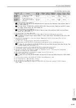

6.2 List of Servo Parameters
6-25
6
Parameter Li
s
t
s
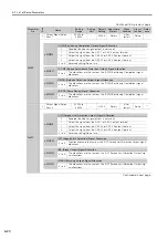
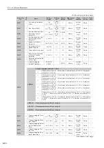
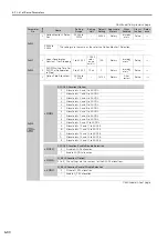
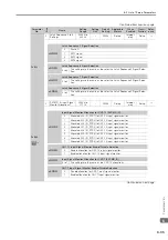
Pn550
2
Analog Monitor 1 Offset
Voltage
-10,000 to
10,000
0.1 V
0
Rotary
Immedi-
ately
Setup
*1
Pn551
2
Analog Monitor 2 Offset
Voltage
-10,000 to
10,000
0.1 V
0
Rotary
Immedi-
ately
Setup
*1
Pn552
2
Analog Monitor 1 Mag-
nification
-10,000 to
10,000
×
0.01
100
Rotary
Immedi-
ately
Setup
*1
Pn553
2
Analog Monitor 2 Mag-
nification
-10,000 to
10,000
×
0.01
100
Rotary
Immedi-
ately
Setup
*1
Pn55A
2
Power Consumption
Monitor Unit Time
1 to 1,440
1 min
1
Rotary
Immedi-
ately
Setup
−
Pn560
2
Residual Vibration
Detection Width
1 to 3,000
0.1%
400
Rotary
Immedi-
ately
Setup
*1
Pn561
2
Overshoot Detection
Level
0 to 100
1%
100
Rotary
Immedi-
ately
Setup
*1
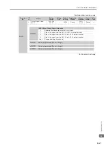
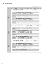
Pn600
2
Regenerative Resistor
Capacity
*5
Depends on
model.
*6
10 W
0
Rotary
Immedi-
ately
Setup
*1
Pn601
2
Dynamic Brake Resis-
tor Allowable Energy
Consumption
0 to 65,535
10 J
0
Rotary
After
restart
Setup
*7
Pn603
2
Regenerative Resis-
tance
0 to 65,535
10 m
Ω
0
Rotary
Immedi-
ately
Setup
*1
Pn604
2
Dynamic Brake Resis-
tance
0 to 65,535
10 m
Ω
0
Rotary
After
restart
Setup
*7
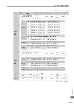
Pn621 to
Pn628
*4
–
Safety Module-Related
Parameters
–
–
–
Rotary
–
–
–
Pn660
2
Preset Position Output
Function Switch
0000h to
0011h
–
0000h
Rotary
After
restart
Setup
–
Continued on next page.
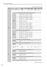
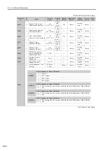
Continued from previous page.
Parameter
No.
Size
Name
Setting
Range
Setting
Unit
Default
Setting
Applicable
Motors
When
Enabled
Classi-
fication
Refer-
ence
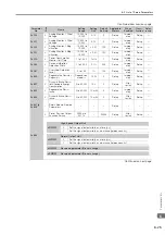
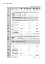
n.
X
High-Speed Output Unit
0
Set the signal output width as a time [
μ
s].
1
Set the signal output width as a distance [reference units].
n.
X
Normal Output Unit
0
Set the signal output width as a time [ms].
1
Set the signal output width as a distance [reference units].
n.
X
Reserved parameter (Do not change.)
n.X
Reserved parameter (Do not change.)