


Index
Index-1
INDEX
Numerics
400-V power supply voltage - - - - - - - - - - - - - - - - - - - - - - - - - 5-18
A
absolute encoder battery - - - - - - - - - - - - - - - - - - - - - - - - - - - - 4-13
AC/DC reactors for harmonic suppression - - - - - - - - - - - - 4-21
,
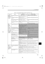
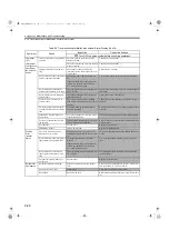
alarm display and troubleshooting - - - - - - - - - - - - - - - - - - - - - - 9-5
alarm display table- - - - - - - - - - - - - - - - - - - - - - - - - - - - - - - - - 9-2
alarm reset - - - - - - - - - - - - - - - - - - - - - - - - - - - - - - - - - - - - - - 9-2
ambient/storage humidity - - - - - - - - - - - - - - - - - - - - - - - - - - - - 3-2
ambient/storage temperature - - - - - - - - - - - - - - - - - - - - - - - - - - 3-2
analog monitor - - - - - - - - - - - - - - - - - - - - - - - - - - - - - - - - - - - 8-5
analog monitor cable - - - - - - - - - - - - - - - - - - - - - - - - - - - - - - 2-24
B
battery case- - - - - - - - - - - - - - - - - - - - - - - - - - - - - - - - - - - - - 4-13
battery for absolute encoder- - - - - - - - - - - - - - - - - - - - - - - - - - 2-25
battery installed on the host controller end - - - - - - - - - - - - - - - - 4-13
brake power supply unit - - - - - - - - - - - - - - - - - - - - - - - - - - - - 4-10
built-in regenerative resistor - - - - - - - - - - - - - - - - - - - - - - - - - 5-20
C
cable selection- - - - - - - - - - - - - - - - - - - - - - - - - - - - - - - - - - - - 2-7
SGMAS and SGMPS servomotors - - - - - - - - - - - - - - - - - - - 2-7
SGMCS servomotors - - - - - - - - - - - - - - - - - - - - - - - - - - - 2-20
SGMSS Servomotor- - - - - - - - - - - - - - - - - - - - - - - - - - - - 2-15
cable type - - - - - - - - - - - - - - - - - - - - - - - - - - - - - - - - - - - - - - - 4-3
cables for analog monitor - - - - - - - - - - - - - - - - - - - - - - - - - - - - 4-8
cables for connecting personal computers - - - - - - - - - - - - - - - - - 4-8
CE marking - - - - - - - - - - - - - - - - - - - - - - - - - - - - - - - - - - - - 1-11
checking products - - - - - - - - - - - - - - - - - - - - - - - - - - - - - - - - - 1-2
CN1 cables for I/O signals - - - - - - - - - - - - - - - - - - - - - - - - - - - 4-6
CN1 terminal layout- - - - - - - - - - - - - - - - - - - - - - - - - - - - - - - - 5-9
CN2 terminal layout- - - - - - - - - - - - - - - - - - - - - - - - - - - - - - - - 5-7
connecting regenerative resistors - - - - - - - - - - - - - - - - - - - - - - 5-20
connectors for main circuit, control power supply,
and servomotor cable - - - - - - - - - - - - - - - - - - - - - - - - - - - - - - - 4-4
continuous output current - - - - - - - - - - - - - - - - - - - - - - - - - - - - 3-2
CSA standards - - - - - - - - - - - - - - - - - - - - - - - - - - - - - - - - - - 1-11
cyclic commands - - - - - - - - - - - - - - - - - - - - - - - - - - - - - - - - - 6-10
cyclic responses- - - - - - - - - - - - - - - - - - - - - - - - - - - - - - - - - - 6-10
D
digital operator - - - - - - - - - - - - - - - - - - - - - - - - - - - - - - - 2-24
E
examples of I/O signal connections- - - - - - - - - - - - - - - - - - - - - - 5-8
external regenerative resistor - - - - - - - - - - - - - - - - - - - - - - - - - 4-11
external regenerative resistors - - - - - - - - - - - - - - - - - - - - - - - - 5-20
F
flexible cables - - - - - - - - - - - - - - - - - - - - - - - - - - - - - - - - - - - 5-23
frequency characteristics- - - - - - - - - - - - - - - - - - - - - - - - - - - - - 3-2
fuse capacity - - - - - - - - - - - - - - - - - - - - - - - - - - - - - - - - - - - - 2-25
G
ground terminal - - - - - - - - - - - - - - - - - - - - - - - - - - - - - - - - - - 4-2
grounding - - - - - - - - - - - - - - - - - - - - - - - - - - - - - - - - - - - - - 5-14
H
hot start - - - - - - - - - - - - - - - - - - - - - - - - - - - - - - - - - - - - - - - 3-12
I
I/O signal
names and functions - - - - - - - - - - - - - - - - - - - - - - - - - - - 5-10
input power supply - - - - - - - - - - - - - - - - - - - - - - - - - - - - - - - - 3-2
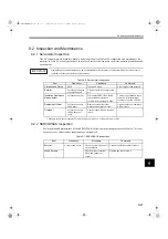
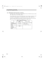
inspection and maintenance - - - - - - - - - - - - - - - - - - - - - - - - - 9-21
J
jog mode operation - - - - - - - - - - - - - - - - - - - - - - - - - - - - - - - - 7-2
L
LED 7-segment display - - - - - - - - - - - - - - - - - - - - - - - - - - - - - 6-9
load moment of inertia - - - - - - - - - - - - - - - - - - - - - - - - - - - - - 3-13
load regulation - - - - - - - - - - - - - - - - - - - - - - - - - - - - - - - - - - - 3-2
M
magnetic contactor - - - - - - - - - - - - - - - - - - - - - - - - - - - - - - - 4-18
main circuit
terminal names and descriptions - - - - - - - - - - - - - - - - - - - - 5-2
wiring examples - - - - - - - - - - - - - - - - - - - - - - - - - - - - - - - 5-4
main circuit power input terminals - - - - - - - - - - - - - - - - - - - - - - 4-2
max. output current - - - - - - - - - - - - - - - - - - - - - - - - - - - - - - - - 3-2
molded-case circuit breaker - - - - - - - - - - - - - - - - - - - - - - - - - 2-25
molded-case circuit breaker (MCCB) - - - - - - - - - - - - - - - - - - - 4-14
monitor mode - - - - - - - - - - - - - - - - - - - - - - - - - - - - - - - - - - -10-10
N
noise filters - - - - - - - - - - - - - - - - - - - - - - - - - - - - - - - - 2-26
noise interference - - - - - - - - - - - - - - - - - - - - - - - - - - - - - - - - 5-12
notch filters - - - - - - - - - - - - - - - - - - - - - - - - - - - - - - - - - - - - - 8-3
P
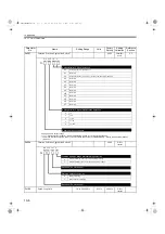
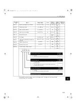
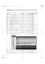
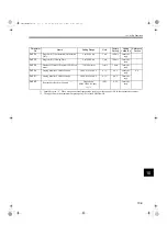
parameter list - - - - - - - - - - - - - - - - - - - - - - - - - - - - - - - - - - - 10-3
peripheral device selection - - - - - - - - - - - - - - - - - - - - - - - - - - 2-24
peripheral devices - - - - - - - - - - - - - - - - - - - - - - - - - - - - - - - - - 4-8
precautions for wiring SynqNet cables - - - - - - - - - - - - - - - - - - - 6-5
Q
Q value - - - - - - - - - - - - - - - - - - - - - - - - - - - - - - - - - - - - - - - - 8-3
R
reactors
connecting a reactor- - - - - - - - - - - - - - - - - - - - - - - - - - - - 5-19
types - - - - - - - - - - - - - - - - - - - - - - - - - - - - - - - - - - - - - - 5-19
recommended noise filters - - - - - - - - - - - - - - - - - - - - - - - - - - 5-14
regenerative resistor capacity - - - - - - - - - - - - - - - - - - - - - - - - 5-21
regenerative resistors - - - - - - - - - - - - - - - - - - - - - - - - - - - - - - 2-27
replacing oil seal - - - - - - - - - - - - - - - - - - - - - - - - - - - - - - - - - 9-21
SIEPS80000025.book 1 ページ 2004年10月25日 月曜日 午前11時57分


