


4 Specifications and Dimensional Drawings of Cables and Peripheral Devices
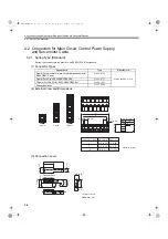
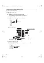
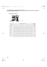
4.4.10 Magnetic Contactor
4-18
4.4.10 Magnetic Contactor
(1) Model:
HI-
J
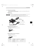
The magnetic contactor is manufactured by Yaskawa Controls Co., Ltd. Contact your Yaskawa representative for
details.
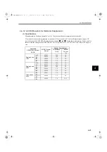
A magnetic contactor is required to make the AC power to SERVOPACK ON/OFF sequence externally. Be sure
to attach a surge protector to the excitation coil of the magnetic contactor. Refer to
for
details of the surge protector.
For selecting a magnetic contactor, refer to
.
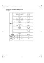
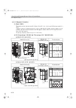
(2) For Single-phase 100/200V and Three-phase 200 V SERVOPACKs
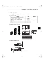
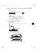
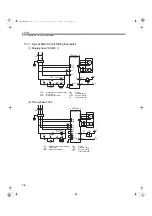
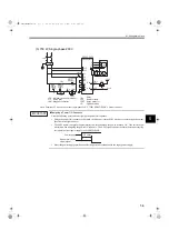
(a) Model: HI-11J and HI-14J
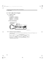
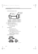
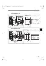
(b) Model: HI-15, HI-18J, and HI-20J
Dimensions in mm (in)
Mounting Hole
Dimensions in mm (in)
Terminal Symbols
Approx mass: 0.25 kg (0.551 lb)
Dimensions in mm (in)
Mounting Hole
Dimensions in mm (in)
Terminal Symbols
Approx. mass: 0.38 kg (0.838 lb)
9 (0.35)
35(1.38)
76 (2.99)
61 (2.40)
34.5 (1.36)
4.5 (0.18)
a
b
2
U
1
R
S
T
44 (1.73)
10.1 (0.40)
13
(0.51)
8.2 (0.32)
41 (1.61)
74.5 (2.93)
78.5 (3.09)
8.2
(0.32)
10.4 (0.41)
4
(0.16)
M3.5 Auxiliary contact terminal
M3.5 Main contact terminal
M3.5 Coil
terminal
V
W
2
×
M4 mounting
holes
34 (1.34)
5
(0.20)
52 (2.05)
48 (1.89)
15.5 (0.61)
1NO
1NC
Auxiliary
contact
Structure
91 (3.58)
35 (1.38)
65 (2.56)
4.5
(0.18)
76 (2.99)
54 (2.13)
9 (0.35)
39 (1.54)
R
S
U
W
V
T
a
b
45.5 (1.79)
15.3 (0.60)
51 (2.01)
8.2
(0.32)
9.6 (0.38)
3
Main contact
terminal M3.5
Coil terminal
M3.5
Auxiliary contact
terminal M3.5
11.3
(0.44)
10.8
(0.43)
9.6
(0.38)
85 (3.35)
50 (1.97)
29 (1.14)
1
2
4
8.2
(0.32)
5.2
(0.20)
35 (1.38)
5 (0.20)
75 (2.95)
70 (2.76)
2
×
M4 mounting
holes
1NO1NC
Auxiliary
contact
Structure
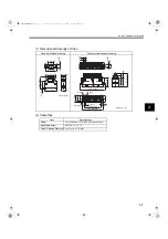
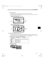
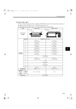
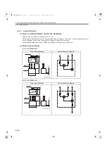
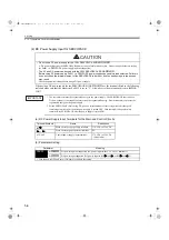
HI-15J
1NO
1NC
HI-20J
A1
a
1
R
3
S
5
T
41
5
23
7
2
U
4
V
6
W
42
6
24
8
b
A2
Auxiliary
contact
Structure
SIEPS80000025.book 18 ページ 2004年10月25日 月曜日 午前11時57分


