


3.2 SERVOPACK Installation
3-5
3
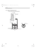
Orientation
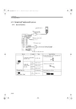
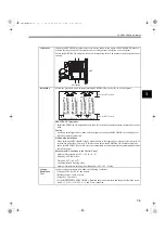
Install the SERVOPACK perpendicular to the wall as shown in the figure. The SERVOPACK must be
oriented this way because it is designed to be cooled by natural convection or a cooling fan.
Secure the SERVOPACK using two to four of the mounting holes. The number of holes depends on the
capacity.
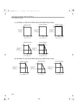
Installation
Follow the procedure below to install multiple SERVOPACKs side by side in a control panel.
SERVOPACK Orientation
Install the SERVOPACK perpendicular to the wall so the front panel containing connectors faces out-
ward.
Cooling
As shown in the figure above, allow sufficient space around each SERVOPACK for cooling by cool-
ing fans or natural convection.
Side-by-side Installation
When installing SERVOPACKs side by side as shown in the figure above, allow at least 10 mm (0.39
in) between and at least 50 mm (1.97 in) above and below each SERVOPACK. Install cooling fans
above the SERVOPACKs to avoid excessive temperature rise and to maintain even temperature inside
the control panel.
Environmental Conditions in the Control Panel
Ambient Temperature: 0 to 55
°
C (32 to 131
°
F)
Humidity: 90% RH or less
Vibration: 0.5 G (4.9 m/s
2
)
Condensation and Freezing: None
Ambient Temperature for Long-term Reliability: 45
°
C (113
°
F) max.
Voltage
Resistance
Test
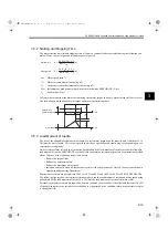
Conduct voltage resistance tests under the following conditions.
• Voltage:1500 Vrms AC for one minute
• Braking current: 30 mA or more
• Frequency: 50 or 60 Hz
• For SGDS-
72A SERVOPACKs: Between the ground terminals and the point where the termi-
nals L1, L2, (L3), L1C, L2C, U, V, and W are connected.
Ventilation
Wall
YASKAWA ELECTRIC
MADE IN JAPAN
30 mm (1.18in) min.
50 mm (1.97in) min.
10 mm (0.39in) min.
50 mm (1.97in) min.
Cooling fan
Cooling fan
SIEPS80000025.book 5 ページ 2004年10月25日 月曜日 午前11時57分


