


Index
Index-2
S
service commands - - - - - - - - - - - - - - - - - - - - - - - - - - - - - - - - 6-11
servo alarm (ALM) output - - - - - - - - - - - - - - - - - - - - - - - - - - - - 9-2
servo system configurations - - - - - - - - - - - - - - - - - - - - - - - - - - - 1-6
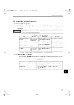
servomotor inspection- - - - - - - - - - - - - - - - - - - - - - - - - - - - - - 9-21
servomotor stop method - - - - - - - - - - - - - - - - - - - - - - - - - - - - - 9-2
servomotors
nameplate - - - - - - - - - - - - - - - - - - - - - - - - - - - - - - - - - - - - 1-2
product part names - - - - - - - - - - - - - - - - - - - - - - - - - - - - - - 1-4
SERVOPACK inspection- - - - - - - - - - - - - - - - - - - - - - - - - - - - 9-21
SERVOPACK main circuit wire size - - - - - - - - - - - - - - - - - - - - - 4-2
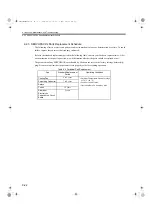
SERVOPACK standard replacement period - - - - - - - - - - - - - - - 9-22
SERVOPACK’s parts replacement schedule - - - - - - - - - - - - - - - 9-22
SERVOPACKs
applicable servomotors - - - - - - - - - - - - - - - - - - - - - - - - - - - 2-6
dimensional drawings - - - - - - - - - - - - - - - - - - - - - - - - - - - 3-17
installation - - - - - - - - - - - - - - - - - - - - - - - - - - - - - - - - - - - 3-4
internal block diagrams - - - - - - - - - - - - - - - - - - - - - - - - - - - 3-6
load moment of inertia - - - - - - - - - - - - - - - - - - - - - - - - - - 3-12
model designations- - - - - - - - - - - - - - - - - - - - - - - - - - - - - - 2-5
nameplate - - - - - - - - - - - - - - - - - - - - - - - - - - - - - - - - - - - - 1-3
overload characteristics - - - - - - - - - - - - - - - - - - - - - - - - - - 3-12
power losses - - - - - - - - - - - - - - - - - - - - - - - - - - - - - - - - - 3-11
product part names - - - - - - - - - - - - - - - - - - - - - - - - - - - - - - 1-5
ratings and specifications- - - - - - - - - - - - - - - - - - - - - - - - - - 3-2
speed control range- - - - - - - - - - - - - - - - - - - - - - - - - - - - - - - - - 3-2
starting time - - - - - - - - - - - - - - - - - - - - - - - - - - - - - - - - - - - - 3-13
stopping time- - - - - - - - - - - - - - - - - - - - - - - - - - - - - - - - - - - - 3-13
supported SynqNet features - - - - - - - - - - - - - - - - - - - - - - - - - - 6-10
surge protector- - - - - - - - - - - - - - - - - - - - - - - - - - - - - - - - - - - 4-20
switch ID setting - - - - - - - - - - - - - - - - - - - - - - - - - - - - - - - - - - 6-8
SynqNet communications
grounding - - - - - - - - - - - - - - - - - - - - - - - - - - - - - - - - - - - - 6-7
specifications and configurations - - - - - - - - - - - - - - - - - - - - 6-4
SynqNet communications connection example - - - - - - - - - - - - - - 6-4
SynqNet connectors (CN6A and CN6B) - - - - - - - - - - - - - - - - - 5-11
SynqNet packet timing - - - - - - - - - - - - - - - - - - - - - - - - - - - - - - 6-2
SynqNet port LED indicators - - - - - - - - - - - - - - - - - - - - - - - - - - 6-8
T
temperature regulation - - - - - - - - - - - - - - - - - - - - - - - - - - - - - - 3-2
temperature-resistant vinyl cable- - - - - - - - - - - - - - - - - - - - - - - - 4-3
torque control tolerance- - - - - - - - - - - - - - - - - - - - - - - - - - - - - - 3-2
torque filters - - - - - - - - - - - - - - - - - - - - - - - - - - - - - - - - - - - - - 8-2
trial operation - - - - - - - - - - - - - - - - - - - - - - - - - - - - - - - - - - - - 7-2
troubleshooting - - - - - - - - - - - - - - - - - - - - - - - - - - - - - - - - - - - 9-2
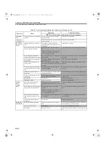
troubleshooting for malfunction without alarm display- - - - - - - - 9-17
U
UL standards - - - - - - - - - - - - - - - - - - - - - - - - - - - - - - - - - - - - 1-11
using more than one SERVOPACK - - - - - - - - - - - - - - - - - - - - - 5-17
using noise filter - - - - - - - - - - - - - - - - - - - - - - - - - - - - - - - - - 5-14
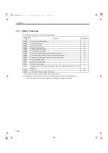
utility functions - - - - - - - - - - - - - - - - - - - - - - - - - - - - - - - - - - 10-2
V
vibration/shock resistance - - - - - - - - - - - - - - - - - - - - - - - - - - - - 3-2
vinyl cable - - - - - - - - - - - - - - - - - - - - - - - - - - - - - - - - - - - - - - 4-3
voltage regulation- - - - - - - - - - - - - - - - - - - - - - - - - - - - - - - - - - 3-2
voltage resistance test - - - - - - - - - - - - - - - - - - - - - - - - - - - - - - - 3-5
W
warning display and troubleshooting- - - - - - - - - - - - - - - - - - - - 9-15
warning displays - - - - - - - - - - - - - - - - - - - - - - - - - - - - - - - - - - 9-4
wiring for noise control - - - - - - - - - - - - - - - - - - - - - - - - - - - - 5-13
wiring main circuit terminal block - - - - - - - - - - - - - - - - - - - - - - 5-3
wiring precautions - - - - - - - - - - - - - - - - - - - - - - - - - - - - - - - - 5-12
SIEPS80000025.book 2 ページ 2004年10月25日 月曜日 午前11時57分


