15.3 Warning Displays
15.3.2 Troubleshooting Warnings
15-46
Note: 1. A warning code is not output unless you set Pn001 (2001 hex) to n.1
(Output both alarm codes and
warning codes).
2. Use Pn008 (2008 hex) = n.
X
(Warning Detection Selection) to control warning detection.
However, the following warnings are not affected by the setting of Pn008 (2008 hex) = n.
X
and other
parameter settings are required in addition to Pn008 (2008 hex) = n.
X
.
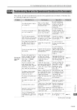
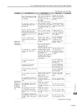
15.3.2
Troubleshooting Warnings
The causes of and corrections for the warnings are given in the following table. Contact your
Yaskawa representative if you cannot solve a problem with the correction given in the table.
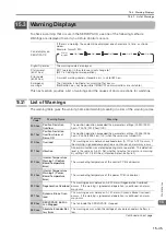
942 hex
Speed Ripple Com-
pensation Information
Disagreement
The speed ripple compensation information stored in the encoder does
not agree with the speed ripple compensation information stored in the
SERVOPACK.
971 hex
Undervoltage
This warning occurs before an A.410 alarm (Undervoltage) occurs. If the
warning is ignored and operation is continued, an alarm may occur.
9A0 hex
Overtravel
Overtravel was detected while the servo was ON.
9b0 hex
Preventative Mainte-
nance Warning
One of the consumable parts has reached the end of its service life.
Warning
Parameters That Must Be Set to Select Warning Detection
Reference
911 hex
Pn310 (2310 hex) = n.
X (Vibration Detection Setting)
930 hex
Pn008 (2008 hex) = n.
X (Low Battery Voltage Alarm/Warning
Selection)
942 hex
Pn423 (2423 hex) = n.
X
(Speed Ripple Compensation Information
Disagreement Warning Detection Selection)
971 hex
Pn008 (2008 hex) = n.
X
(Function Selection for Undervoltage)
(Not affected by the setting of Pn008 (2008 hex) = n.
X
.)
9A0 hex
Pn00D (200D hex) = n.X
(Overtravel Warning Detection Selection)
(Not affected by the setting of Pn008 (2008 hex) = n.
X
.)
9b0 hex
Pn00F (200F hex) = n.
X (Preventative Maintenance Selection)
Continued from previous page.
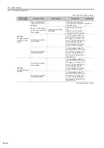
Warning
Code
Warning Name
Meaning
Warning Number:
Warning Name
Possible Cause
Confirmation
Correction
Reference
900 hex:
Position Deviation
Overflow
The Servomotor
U, V, and W wiring
is not correct.
Check the wiring of the
Servomotor’s Main Cir-
cuit Cables.
Make sure that there are no
faulty connections in the
wiring for the Servomotor
and encoder.
–
A SERVOPACK
gain is too low.
Check the SERVO-
PACK gains.
Increase the servo gain,
e.g., by using autotuning
without a host reference.
The acceleration
of the position ref-
erence is too high.
Reduce the reference
acceleration and try
operating the SERVO-
PACK.
Reduce the acceleration of
the position reference using
an EtherCAT command.
–
The excessive
position deviation
alarm level (Pn520
(2520 hex) ×
Pn51E (251E
hex)/100) is too
low for the operat-
ing conditions.
Check excessive posi-
tion deviation alarm
level (Pn520 (2520 hex)
× Pn51E (251E hex)/
100) to see if it is set to
an appropriate value.
Optimize the settings of
Pn520 (2520 hex) and
Pn51E (251E hex).
A failure occurred
in the SERVO-
PACK.
–
Turn the power supply to
the SERVOPACK OFF and
ON again. If an alarm still
occurs, the SERVOPACK
may be faulty. Replace the
SERVOPACK.
–
Continued on next page.

